Isel LES4 Assembly Instruction Manual
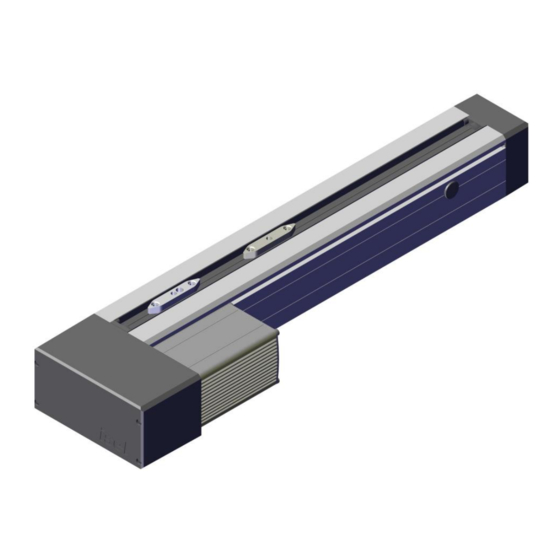
Ball screw unit with spindle drive
Hide thumbs
Also See for LES4:
- Assembly instructions manual (52 pages) ,
- Assembly instructions manual (43 pages)
Table of Contents
Advertisement
Quick Links
Advertisement
Table of Contents

Subscribe to Our Youtube Channel
Related Manuals for Isel LES4

Summary of Contents for Isel LES4
- Page 2 Assembly instruction linear unit LES4, 5, 6 ball screw unit with spindle drive. Serial number:...
- Page 3 Item number: 234xxx xxxx...
- Page 4 LES 4, 5, 6 - 234xxx xxxx Manufacturer: isel Germany AG Bürgermeister-Ebert-Str., 40 D-36124, Eichenzell +49 6659 981 800 +49 6659 981 782 automation@isel.com www.isel.com Board: Hugo Isert, Werner Kister Supervisory board: Gunter Zumpf, Lars Rohrlack-Soth, Marcus Walter-Krisch Commercial Register, Register Court Fulda...
- Page 5 LES 4, 5, 6 - 234xxx xxxx revision date of change reason for change changed by index 05.07.2019 first version Bley.Christian 5 / 62 Assembly instruction...
-
Page 6: Table Of Contents
LES 4, 5, 6 - 234xxx xxxx Contents 1 General information ....................10 Importance of the documentation ....................10 Scope of delivery ........................10 Co-Applicable Documents ......................11 Declaration of incorporation according to Machinery directive 2006/42/EC Annex II B ....12 General data, contact persons .................... - Page 7 LES 4, 5, 6 - 234xxx xxxx 7 Maintenance, repair ....................54 Cleaning ............................. 54 Lubrication ..........................54 Maintenance plan ........................56 Troubleshooting ......................... 57 8 Dismantling and disposal ................... 58 9 Spare parts overview ....................59 7 / 62 Assembly instruction...
- Page 8 LES 4, 5, 6 - 234xxx xxxx List of figures Fig. 1 - Linear guide LFS 12-2 with guide carriage WS 5 ........................18 Fig. 2 - LES 4with belt drive module or prepared for direct drive ......................19 Fig. 3 - Ordering key LES 4................................... 19 Fig.
- Page 9 LES 4, 5, 6 - 234xxx xxxx List of tables Table 1 - General faults on the linear unit ............................57 Table 2 - Spare parts LES 4, 5, 6Direct drive ............................59 Table 3 - Spare parts LES 4, 5, 6Belt drive ............................59 Table 4 - Spare parts LES 4, 5, 6 Direct drive ............................
-
Page 10: General Information
If you notice misprints or errors or you see ways to improve our technical documentation, we are grateful for any hint or suggestion! © isel Germany AG, 2021-02-23. All rights reserved. Importance of the documentation These Assembly instruction and the associated documentation are an integral part of the linear unit. The operator is obliged to keep the Assembly instruction for the entire service life of the linear unit and to grant access to the personnel working with the machine. -
Page 11: Co-Applicable Documents
/<number>/ can be found as the leading number in the file name of the document. Applicable documentsisel Germany AG No. Document Dimensional drawing Operating Instructions Positioning module IMD20/ IMD40 with CANopen interface: isel Germany AG, 12/2018 Applicable documents from other manufacturers 11 / 62 Assembly instruction... -
Page 12: Declaration Of Incorporation According To Machinery Directive 2006/42/Ec Annex Ii B
The commissioning of the incomplete machine (product) is prohibited until the machine in which this product has been incorporated or of which it is a component complies with the requirements of all relevant directives (especially MRL ) and this complete machine has a CE marking. Eichenzell, 23.02.2021 Werner Kister, Chairperson isel Germany AG 12 / 62 Assembly instruction... -
Page 13: General Data, Contact Persons
LES 4, 5, 6 - 234xxx xxxx General data, contact persons Client Operator (if different from the client) Manufacturer isel Germany AG Bürgermeister-Ebert-Str., 40 D-36124, Eichenzell +49 6659 981 800 +49 6659 981 782 automation@isel.com You can reach our contact persons for the technical consultancy and the sale as well as the service under the following contact data. -
Page 14: Explanation Of Symbols And Instructions
LES 4, 5, 6 - 234xxx xxxx Explanation of symbols and instructions Notes on hazards that occur in connection with work on the machine are marked as follows in these operating instructions. They warn you of possible personal injury or property damage or give you work aids. NOTE If, in the event of a dangerous situation, the maximum result of an accident is a damage to property, the notice bears the "NOTE"... -
Page 15: List Of Abbreviations
European Norm Harmonised European Standard International Organization for International Organization for Standardization Standardization Linear unit with spindle drive (LES4, LES5 Components used in the machine. and LES6) Two synchronously running linear or rotary units Gantry also called gantry mode or gantry axis... -
Page 16: Symbols Used In The Operating Instructions And On The Machine
LES 4, 5, 6 - 234xxx xxxx Symbols used in the operating instructions and on the machine The use of the symbols is in accordance with the valid regulations of the country of operation. warning symbol description General warning sign Warning against hand injuries Warning of danger of pulling in Warning against hot surfaces... -
Page 17: Overview
LES 4, 5, 6 - 234xxx xxxx Overview General information In this chapter you will first get an overview of the mechanical design, the installation or assembly of the linear units as well as a description of the mode of operation. Then the various linear units are explained in detail. The instructions for commissioning / parameterization and user programming of the axis system depend on the motors used, the corresponding controllers with output stages and their documentation. -
Page 18: Versions Of The Linear Units Of Theles Series
(7) with ball return system (1) and the balls (4) as rolling elements. The balls make the connection between spindle and nut by rolling in the raceways of the ball screw spindle and the ball screw nut. Ball screw nuts of isel Germany AG have several ball circuits with internal ball returns. -
Page 19: Linear Unit Les 5
LES 4, 5, 6 - 234xxx xxxx Design variants LES 4 Fig. 2 - LES 4with belt drive module or prepared for direct drive Ordering key LES 4 Fig. 3 - Ordering key LES 4 2.3.2 Linear unit LES 5 Normally the linear unit LES 5 are delivered without drive module. -
Page 20: Linear Unit Les 6
LES 4, 5, 6 - 234xxx xxxx Design variants LES 5 Fig. 4 - LES 5with integrated belt drive module or prepared for direct drive Ordering key LES 5 Fig. 5 - Ordering keyLES 5 2.3.3 Linear unit LES 6 Normally the linear unit LES 6 are delivered without drive module. -
Page 21: Technical Data
LES 4, 5, 6 - 234xxx xxxx Design variants LES 6 Fig. 6 - LES 6 with belt drive module or prepared for direct drive Ordering key LES 6 Fig. 7 - Ordering key LES 6 Technical data 2.4.1 Mechanical data and dimensions 2.4.1.1 Linear unit LES 4 Linear unit LES 4 Unit... - Page 22 LES 4, 5, 6 - 234xxx xxxx cross-sectional area 18.81 Temperature range bearing °C 0-40 Temperature range operation °C 0 - 60 (80) relative air humidity 90 (non-condensing) Weight linear unit kg/m Weight linear unit and spindle kg/m Shaft slides Shaft slides 1x WS 5 - 70 / 2x WS 5 - 70 Weight shaft slides...
- Page 23 LES 4, 5, 6 - 234xxx xxxx Load factors Fig. 9 - Load diagramLES 4 LES 4 with a WS 5/70 LES 4 with two WS 5/70 3303 N 4955 N 1873 N 2810 N stat. 2821 N 4232 N dyn.
- Page 25 LES 4, 5, 6 - 234xxx xxxx 2.4.1.1.2 Dimension sheet LES 4 - Belt drive according to TE2465 24 / 62 Assembly instruction...
- Page 27 LES 4, 5, 6 - 234xxx xxxx 2.4.1.2 Linear unit LES 5 Linear unit LES 5 Unit Value Aluminium profile WxH 225 x 75 Profile lengths 290 - 2990 Material AIMgSiO, 5F22 Anodizing E6/EV1 Spindle pitch 2.5 / 4 / 5 / 10 / 20 Repeat accuracy 0.02 Moment of inertia...
- Page 28 LES 4, 5, 6 - 234xxx xxxx Bending Fig. 10 - Deflection data LES 5 Load factors Fig. 11 - Load diagramLES 5 LES 5with two WS 5/70 LES 5 with four WS 5/70 4955 N 6606 N 2810 N 3746 N stat.
- Page 29 LES 4, 5, 6 - 234xxx xxxx 1990 1650 2490 1050 2990 2.4.1.2.1 Dimension sheet LES 5 - Preparation for direct drive to TE2480 27 / 62 Assembly instruction...
- Page 31 LES 4, 5, 6 - 234xxx xxxx 2.4.1.2.2 Dimension sheet LES 5 - Integrated belt drive according to TE2478 28 / 62 Assembly instruction...
- Page 33 LES 4, 5, 6 - 234xxx xxxx 2.4.1.3 Linear unit LES 6 29 / 62 Assembly instruction...
- Page 34 LES 4, 5, 6 - 234xxx xxxx Linear unit LES 6 Unit Value Aluminium profile WxH 150 x 75 Profile lengths 290 - 2990 Material AIMgSiO, 5F22 Anodizing E6/EV1 Spindle pitch 2.5 / 4 / 5 / 10 / 20 Repeat accuracy 0.02 Moment of inertia...
-
Page 35: Fig. 12 - Deflection Data Les
LES 4, 5, 6 - 234xxx xxxx Bending Fig. 12 - Deflection data LES Load factors Fig. 13 - Load diagram LES LES 6 with two WS 5/70 LES 6 with four WS 5/70 4955 N 6606 N 2810 N 3746 N stat. - Page 36 LES 4, 5, 6 - 234xxx xxxx 1990 1650 2490 1050 2990 2.4.1.3.1 Dimension sheet LES 6 - Preparation direct drive according to TE2481 32 / 62 Assembly instruction...
-
Page 38: Ambient Conditions
Industrial Safety and Health (BetrSichV) or other national requirements in the country of operation. Type plate The type plate is attached to the front left of the machine. Maintain the type plate in readable condition. linear unit LES4, 5, 6 item no.: 234xxx xxxx Prod. date: Serial no.:... -
Page 40: Fig. 14 - Type Plate
LES 4, 5, 6 - 234xxx xxxx Fig. 14 - Type plate 34 / 62 Assembly instruction... -
Page 41: Safety
LES 4, 5, 6 - 234xxx xxxx Safety This chapter informs you about possible dangers and about your protection options against these dangers when handling the machine. You will receive information on personal and accident protection and on safety-related behaviour when working with this machine. -
Page 42: Intended Use
● the use of the linear unit exclusively in technically correct condition. ● the compliance with the intervals specified in the maintenance plan. ● to use only materials and accessories, approved by isel Germany AG as well as the spare parts listed in the Assembly instruction ●... -
Page 43: Reasonably Foreseeable Misuse
● Do not install the product near equipment that generates strong electromagnetic fields. This could interfere with the function. Avoid environments with direct sunlight, intense heat, cold, humidity or wetness. ● Only accessories and spare parts approved by isel Germany AG may be used in order to avoid personal hazards due to unsuitable spare parts. -
Page 44: Special Safety Instructions
LES 4, 5, 6 - 234xxx xxxx ● Never disassemble the product. ● Parts of the product can become very hot during the operation. Allow these parts to cool before touching. ● Do not place any loose objects on the product. 3.3.2 Special safety instructions You have to work on and with the machine exclusively with authorised, trained and instructed personnel. -
Page 45: Fire Protection
LES 4, 5, 6 - 234xxx xxxx NOTE! Transport Non-observance of the safety instructions may result in damage to property and/or personal injury! Please observe the transport instructions. ˃ During transport, support the product only in the designated places. ˃ Observe the weight and use suitable and tested load carrying equipment for lifting and ˃... -
Page 46: Personal Protective Equipment
LES 4, 5, 6 - 234xxx xxxx Personal Protective Equipment In the following chapters, the operating instructions explicitly describe the use of the personal protective equipment. WARNING! Do not wear personal protective equipment! If you do not wear the specified personal protective equipment or you use faulty personal protective equipment, you may be involved in an occupational accident. -
Page 47: Transport
LES 4, 5, 6 - 234xxx xxxx Transport Below you will find information on how to transport the machine correctly, without damaging it and without endangering persons. NOTE! Improper lifting of the linear unit If you do not lift the linear unit correctly, damage may occur due to deflection! If you do not lift the linear unit correctly, injuries to the musculoskeletal system may occur due to incorrect lifting! Find out about the weight of the unit. -
Page 48: Assembly And Commissioning
LES 4, 5, 6 - 234xxx xxxx Assembly and commissioning Assembly Mounting on the guide profile Free positioning Fig. 15 - linear unit LES 4, 5, 6 for installation as free standing You can place the linear unit on a frame, a work table or any other suitable stable base. Select the installation location so that the product cannot fall down by itself or by an impact or pulling on the cable. -
Page 49: Fig. 17 - Linear Unit Les 4, 5, 6 For Foot Mounting
LES 4, 5, 6 - 234xxx xxxx Ensure that the mounting surfaces are sufficiently clean. The used aluminium profiles are extruded profiles which, due to the manufacturing process, showed deviations in terms of straightness and torsion. The tolerance of this deviation is defined in DIN EN 12020-2. linear unit are face milled and therefore these deviations are usually undercut. -
Page 50: Fig. 18 - Linear Unit Les 4, 5, 6 For Mounting The Carriage
LES 4, 5, 6 - 234xxx xxxx Mounting on the guide carriages Carriage mounting Fig. 18 - linear unit LES 4, 5, 6 for mounting the carriage The guide carriages have tapped holes - M6 - for fastening transport loads to the guide carriages. Fitting holes 6h7 enable precise positioning and reproducibility of the mounting position. -
Page 51: Fig. 20 - Linear Unit Les 4, 5, 6 For Slide Plate Mounting - Frame
LES 4, 5, 6 - 234xxx xxxx Slide plate mounting Fig. 20 - linear unit LES 4, 5, 6 for slide plate mounting - frame Laterally protruding carriage plates enable the guide carriages to be fixed to the frame and thus enable linear movement of the linear guide rail relative to the frame. -
Page 52: Commissioning
LES 4, 5, 6 - 234xxx xxxx Belt drive modules Fig. 22 - Mounting belt drive module The picture above shows the assembly of a belt drive module. The pulleys must have the same pitch as the toothed belt. Both shaft ends and the pulleys should be free of burrs, rust and dirt. As shaft-hub connection, we recommend forceful connections using clamping bushes. - Page 53 LES 4, 5, 6 - 234xxx xxxx Incorrect installation (including loading of the axis system), cabling or commissioning increases the risk. 47 / 62 Assembly instruction...
-
Page 54: Mounting Parts
LES 4, 5, 6 - 234xxx xxxx Mounting parts In this chapter you will find information about the components that are mounted when your axis is delivered. Motor modules Various drive modules with stepper motors and servo motors are offered as standard for the LESlinear unit. These can be mounted either directly via a coupling, spacer and adapter flange in extension of the ball screw spindle or laterally or integrated by means of a toothed belt step. - Page 55 LES 4, 5, 6 - 234xxx xxxx Direct drive LES 4 / 5 / 6 Item-No. EC servo motor EC 60 TM 200W 48V 396421 0060 103.5 EC servo motor EC 60 TM 200W 48V with brake 396421 0260 150.5 EC servo motor EC 60 TM 200W 310V 396421 0070 107.7...
-
Page 56: Sliding Plates
LES 4, 5, 6 - 234xxx xxxx EC servo motor EC 60 TM 200W 48V 396421 1060 EC servo motor EC 60 TM 200W 48V with brake 396421 1260 EC servo motor EC 60 TM 200W 310V 396421 1070 EC servo motor EC 60 TM 200W 310V with brake 396421 1270 EC servo motor EC 60 TM 400W 48V 396440 1080... -
Page 58: Other Options
LES 4, 5, 6 - 234xxx xxxx Other options 6.3.1 External limit switches Fig. 23 - external limit switches LES Limit switch mounting kit for Limit switch mounting kit for Limit switch mounting kit for LES 4 LES 5 LES 6 Item number 216460 0001 216460 0002... - Page 59 LES 4, 5, 6 - 234xxx xxxx Mounting a gas spring attachment kit on a LES 5 The following exploded drawing shows the assembly of the gas spring attachment kit to thelinear unitLES 5. Please note that the connecting plate VP2 (4) is already mounted or must be mounted on the guide carriages (accessories - carriage plates).
-
Page 60: Angular Transmission
LES 4, 5, 6 - 234xxx xxxx 6.3.3 Angular transmission The angular transmission is available in two installation variants for LES4, 5, 6 with direct drive. 1 - angular transmission 2 - split coupling housing with shaft coupling WK 40/60 3 - LES4, 5, 6 4 - Coupling for transmission shaft Ø... -
Page 61: Maintenance, Repair
Installation of manufactured components which have not been produced by isel Germany In this case, isel Germany AGis liable for any personal injury and property damage. Make sure that the safety devices are regularly maintained and checked for proper functioning. - Page 62 Directive 93/112/EEC and ISO 11014-1 can be requested from the manufacturer. Relubrication For relubrication of linear bearings with shafts, only the special grease of isel Germany AG should be used. Oil lubrication is possible and reduces heating at higher spindle speeds, but the mounting position must be observed and the lubrication intervals are shortened every 40 to 60 operating hours.
-
Page 63: Maintenance Plan
Cleaning the linear unit 300 - 700 Operating hours Relubrication guide carriage and ball screw nut with special grease from isel Germany AG monthly - Visual inspection of linear guide rail - wear - Visual inspection of the toothed belt (tension, abrasion...) -
Page 64: Troubleshooting
LES 4, 5, 6 - 234xxx xxxx Troubleshooting The table below includes some general solutions to potential problems occurring when using the machine; they can be rectified independently by the operator if necessary. Information If the problem can not be solved, please get in touch with the maintenance personnel or contact our service/support department. -
Page 65: Dismantling And Disposal
LES 4, 5, 6 - 234xxx xxxx Dismantling and disposal Information Only after all work required for decommissioning and after approval by an authorized specialist, the dismantling operations may be started. Under disassembly you can find the definition of the the dismantling of the machine for the implementation on another positioning location or for scrapping. -
Page 66: Spare Parts Overview
LES 4, 5, 6 - 234xxx xxxx Spare parts overview Spare parts LES4, 5, 6 Quantity Item-No. Designation 623065 0001 Locking nut for KG nut Ø 16 21113x xxxx Ball screw spindle Ø 16 61310x xxxx Ball screw nut Ø 28... -
Page 67: Table 4 - Spare Parts Les 4, 5, 6 Direct Drive
616002 Toothed belt wheel Z25 AT5 611999 2000 Spindle support from L=1490 mm Table 5 - Spare parts LES 4, 5, 6 Belt drive Spare parts LES4, 5, 6 Quantity Item-No. Designation 623065 0001 Locking nut for ball screw nut Ø 16 21113x 5xxx Ball screw spindle Ø... -
Page 68: Table 7 - Spare Parts Les
LES 4, 5, 6 - 234xxx xxxx 623072 0014 Shaft slide WS 5 for ball screw nut 623072 0013 Shaft slide WS 5 without ball screw nut 623065 6913 Bearing flange counter bearing side, incl. deep groove ball bearing 623065 0102 Flange for belt drive 613502 Wiper ball screw nut...
Need help?
Do you have a question about the LES4 and is the answer not in the manual?
Questions and answers