Table of Contents
Advertisement
Quick Links
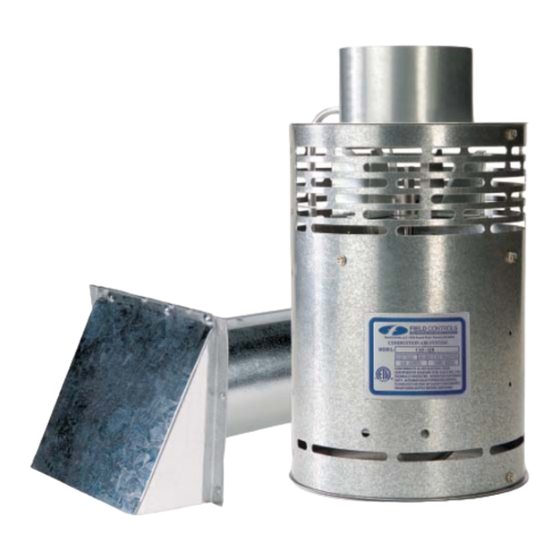
COMBUSTION AIR SYSTEM
This product is designed for use with any natural gas or LP burning furnace, water heater, or boiler with a
24 VAC control system. It may be used with a residential water heater with additional hardware. It may
also be used with more than one appliance. The CAS unit mechanically draws air into a structure and
disperses it near the combustion air intake of an appliance. Refer to Diagram A and Table 1 for guidance
in setting up the CAS system based on the size and length of the connecting ductwork and the input rating
of the appliance.
WARNING! CONNECTIONS TO MULTIPLE APPLIANCES MUST FOLLOW INSTALLATION INSTRUCTION
WARNING! CONNECTIONS TO MULTIPLE APPLIANCES MUST FOLLOW INSTALLATION INSTRUCTION
WIRING DIAGRAMS. FOR HELP CALL 1-800-742-8368.
WIRING DIAGRAMS. FOR HELP CALL 1-800-742-8368.
READ THESE INSTRUCTIONS CAREFULLY AND COMPLETELY BEFORE PROCEEDING WITH THE INSTALLATION.
This device MUST be installed by a qualifi ed agency in accordance with the manufacturer's installation instructions. The defi nition of
a qualifi ed agency is: any individual, fi rm, corporation or company which either in person or through a representative is engaged
in, and is responsible for, the installation and operation of HVAC appliances, who is experienced in such work, familiar with all the
precautions required, and has complied with all the requirements of the authority having jurisdiction.
Installed By:
MODEL: CAS-4JR
ITEMS INCLUDED IN KIT:
1- CAS fan unit
1- 4" galvanized intake Air Vent Hood
2- Mounting brackets to secure the CAS to a wall
2- Wire/conduit connector(s)
1- Instruction Sheet
Please retain these instructions after installation.
Phone:
www.fi eldcontrols.com
Installation Date:
P/N 46527900 Rev C 03/17
Advertisement
Table of Contents

Subscribe to Our Youtube Channel
Related Manuals for Field Controls CAS-4JR


Summary of Contents for Field Controls CAS-4JR
- Page 1 COMBUSTION AIR SYSTEM MODEL: CAS-4JR This product is designed for use with any natural gas or LP burning furnace, water heater, or boiler with a 24 VAC control system. It may be used with a residential water heater with additional hardware. It may also be used with more than one appliance.
- Page 2 GENERAL SYSTEM OPERATION 1. The thermostat (wall thermostat, or Aquastat) calls for heat and energizes a relay which activates the CAS unit. After the CAS fan has come up to speed, an internal air pressure switch closes and completes the circuit to allow the burner to fi...
- Page 3 6" Pipe 50,000 60,000 70,000 80,000 90,000 100,000 110,000 CAS-4JR SIZING CHART Max. equivalent length of 6" pipe available when using the 4" CAS hood Max. equivalent length of 4" pipe available when using the 4" CAS hood 50,000 60,000 70,000...
- Page 4 INSTALLATION PLACEMENT OF THE CAS UNIT The motorized CAS unit should be located on a fl at horizontal surface within the same space as the appliance and within 3' of the combustion air intake. Two mounting brackets are provided for securing the unit against a solid structure, such as a wall, column, or the side of the appliance itself.
- Page 5 The references to various series of control kits implies that any kit in that series may be used. If further information or additional wiring diagrams are needed please consult Field Controls' technical support. WARNING: To reduce the risk of fi re or electric shock, do not use this fan with any solid-state speed control device.
- Page 6 White Common Black White White White Black Figure 5 - Power Vent Single 24V Furnace Black White Black Figure 6 - Chimney Vent 24V Furnace and 30mV Water Heater with CK-20FV or CK-20FG P/N 46527900 Rev C 03/17 page 6 of 8...
- Page 7 Figure 8 - Power Vent Single 24V Boiler Figure 7 - Chimney Vent 24V Boiler Figure 9 page 7 of 8 P/N 46527900 Rev C 03/17...
- Page 8 6" Intake Hood (not included) 46233300 Controls Technical Support at 1-800-742-8368. This manual may be downloaded and printed from the Field Controls website (www.fi eldcontrols.com) This manual may be downloaded and printed from the Field Controls website (www.fi eldcontrols.com) WARRANTY...
Need help?
Do you have a question about the CAS-4JR and is the answer not in the manual?
Questions and answers