
Related Manuals for Vecow EMBC-5000 Series

Summary of Contents for Vecow EMBC-5000 Series
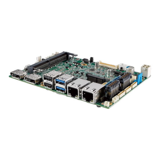
- Page 1 USER USER EMBC-5000 Manual Manual Intel ® Core™ i7/i5/i3 SoC (Tiger Lake UP3) 3.5" Single Board Computer 1 GigE LAN, 2.5G GigE LAN, 4 10G USB, 4 COM, SUMIT A, B, TPM, Ignition Control 1.0.0 Edition 20210318...
- Page 2 Record of Revision Version Date Remark Page Description 1.00 2021/03/18 Official Release ©Vecow EMBC-5000 User Manual...
- Page 3 This manual is released by Vecow Co., Ltd. for reference purpose only. All product offerings and specifications are subject to change without prior notice. It does not represent commitment of Vecow Co., Ltd. Vecow shall not be liable for direct, indirect, special, incidental, or consequential damages arising out of the use of the product or documentation or any infringements upon the rights of third parties, which may result from such use.
- Page 4 Core™ i5-1145G7E Processor (Tiger Lake UP3), DDR4 SO-DIMM, 1 GigE LAN, 2.5GigE LAN, 2 10G USB, 6 USB 2.0, EMBC-5000-1145G7E 4 COM RS-232/422/485, 2 SATA, 9V to 55V DC-in, Ignition Control, High Performance, Fanless, Extended Temperature ©Vecow EMBC-5000 User Manual...
- Page 5 Part Number Description 61-13Q1009-0DA COM Port Cable 61-1300011-100 SATA Data Cable 61-13P0430-08A SATA Power Cable Heat Sink Heat Sink for EMBC-5000 Series Heat Spreader Heat Spreader for EMBC-5000 Series 61-13T10LM-3CG Audio Cable 61-193102U-156 USB 2.0 Cable ©Vecow EMBC-5000 User Manual...
-
Page 6: Table Of Contents
2.1 Packing List 2.2 Connector/Jumper Locations 2.3 Main Board Jumper Settings 2.4 Ignition Control CHAPTER 3 SYSTEM SETUP 3.1 Installing Heat Spreader 3.2 Installing Heat Sink 3.3 Installing DDR4 SO-DIMM Module 3.4 Installing M.2 3.5 Installing SIM Card ©Vecow EMBC-5000 User Manual... - Page 7 4.5 Security 4.6 Boot Functions 4.7 Save & Exit APPENDIX A : GPIO GUIDE APPENDIX B : Software Functions APPENDIX C : RAID Functions APPENDIX D : Power Consumption APPENDIX E : Supported Memory & Storage List ©Vecow EMBC-5000 User Manual...
-
Page 8: Chapter 1 General Introduction
Vecow EMBC-5000 is a new generation smart and power-efficient compact ® embedded engine. Powered by 11th Gen Intel Core™ i7/i5/i3 processor (Tiger Lake UP3) running with up to 32GB DDR4 memory, Vecow EMBC-5000 is ® ® equipped with advanced Intel Iris Xe Graphics supporting up to 8K resolution;... -
Page 9: Features
• Supports full function SUMIT A, B expansion • 9V to 55V DC wide range Power Input • Ignition Power Control • Easy to customize for low-profile system applications • One-stop SUMIT Expansion Design and Manufacturing Services ©Vecow EMBC-5000 User Manual GENERAL INTRODUCTION... -
Page 10: Product Specification
• 1 DDR4 SO-DIMM Socket • 1 LVDS Connector • 1 LVDS Backlight Connector • 2 USB 2.0 Wafer with 4 ports (Optional) • 2 SATA Data Connector • 1 SATA Power Connector • 1 4-pin Fan Connector ©Vecow EMBC-5000 User Manual GENERAL INTRODUCTION... - Page 11 351 g (0.77 lb) Environment Operating Temperature -40°C to 75°C (-40°F to 167°F) Storage Temperature -40°C to 85°C (-40°F to 185°F) Humidity 5% to 95% humidity, non-condensing Relative Humidity 95% at 75°C CE, FCC ©Vecow EMBC-5000 User Manual GENERAL INTRODUCTION...
-
Page 12: Specifications Of Embc-5000-1185G7E
• 1 DDR4 SO-DIMM Socket • 1 LVDS Connector • 1 LVDS Backlight Connector • 2 USB 2.0 Wafer with 4 ports (Optional) • 2 SATA Data Connector • 1 SATA Power Connector • 1 4-pin Fan Connector ©Vecow EMBC-5000 User Manual GENERAL INTRODUCTION... - Page 13 351 g (0.77 lb) Environment Operating Temperature -40°C to 75°C (-40°F to 167°F) Storage Temperature -40°C to 85°C (-40°F to 185°F) Humidity 5% to 95% humidity, non-condensing Relative Humidity 95% at 75°C CE, FCC ©Vecow EMBC-5000 User Manual GENERAL INTRODUCTION...
-
Page 14: Specifications Of Embc-5000-1145G7E
• 1 DDR4 SO-DIMM Socket • 1 LVDS Connector • 1 LVDS Backlight Connector • 2 USB 2.0 Wafer with 4 ports (Optional) • 2 SATA Data Connector • 1 SATA Power Connector • 1 4-pin Fan Connector ©Vecow EMBC-5000 User Manual GENERAL INTRODUCTION... - Page 15 351 g (0.77 lb) Environment Operating Temperature -40°C to 75°C (-40°F to 167°F) Storage Temperature -40°C to 85°C (-40°F to 185°F) Humidity 5% to 95% humidity, non-condensing Relative Humidity 95% at 75°C CE, FCC ©Vecow EMBC-5000 User Manual GENERAL INTRODUCTION...
-
Page 16: Supported Cpu List
1.4 Supported CPU List Processor No. Cores Cache Max. Frequency ECC Memory ® Intel Core™ i7-1185G7E Up to 4.4GHz ® Intel Core™ i5-1145G7E Up to 4.1GHz ©Vecow EMBC-5000 User Manual GENERAL INTRODUCTION... -
Page 17: Mechanical Dimension
1.5 Mechanical Dimension 1.5.1 Dimensions of EMBC-5000 Unit : mm (inch) 146.0 (5.75) 50.2 (1.98) 85.7 (3.38) 5.1 (0.20) 55.2 (2.17) 85.7 (3.38) 1.5.2 Dimensions of Heat Spreader Unit : mm (inch) 148.0 (5.83) 8.5 (0.33) ©Vecow EMBC-5000 User Manual GENERAL INTRODUCTION... -
Page 18: Dimensions Of Heat Sink
1.5.3 Dimensions of Heat Sink Unit : mm (inch) 150.4 (5.92) 25.2 (0.99) 50.2 (1.98) 85.7 (3.38) 50.2 (1.98) 85.7 (3.38) 1.5.4 Dimensions of MB+Heat Spreader Unit : mm (inch) 148.0 (5.83) 8.5 (0.33) ©Vecow EMBC-5000 User Manual GENERAL INTRODUCTION... -
Page 19: Dimensions Of Mb+Heat Sink
1.5.5 Dimensions of MB+Heat Sink Unit : mm (inch) 148.0 (5.83) 21.2 (0.84) ©Vecow EMBC-5000 User Manual GENERAL INTRODUCTION... -
Page 20: Chapter 2 Getting To Know Your Embc-5000
• COM Port Cable • COM Screw#4-40, L=5mm • SATA Data Cable • SATA Power Cable • USB 2.0 Cable • USB Screw PH-M3, L=6mm • Audio Cable • Audio Ring ©Vecow EMBC-5000 User Manual GETTING TO KNOW YOUR EMBC-5000... -
Page 21: Connector/Jumper Locations
M2E_CN1 JDIO2 JDIO1 M2B_CN1 JSEL_DIO JHDD JPS1 JRESET DP_CN1 DP_CN2 LAN2_CON LAN1_CON 2.2.2 Bottom Side View M2B_SIM1 M2B_SIM1 CPU1 LAN2 LAN2 I225-IT CPU1 LED1 LED2 M2B_LED1 M2E_LED1 LED1 LED2 M2B_LED1 M2E_LED1 ©Vecow EMBC-5000 User Manual GETTING TO KNOW YOUR EMBC-5000... - Page 22 The pinouts of Miscellaneous port are listed in following table : JPWBTN JSTATUS JHDD JRESET Group Pin No. Description JPWBTN FP_PWR_BTN_IN JRESET FP_RST_BTN_N PWR_LED_N JSTATUS PWR_LED_P HDD_LED_N JHDD HDD_LED_P ©Vecow EMBC-5000 User Manual GETTING TO KNOW YOUR EMBC-5000...
- Page 23 The EMBC-5000's real-time clock is powered by a lithium battery. It is equipped with Panasonic BR2032 190mAh lithium battery. It is recommended that you not replace the lithium battery on your own, but if the battery needs to be changed, please contact the Vecow RMA service team. Pin No. Function +3V_BAT 2.2.5 CN5 : Audio Connector...
- Page 24 The pin assignments of JUSB1 and JUSB2 are listed in the following table : Pin No. Definition Pin No. Definition JUSB1 USB_VCC USB_VCC USB_VCC USB_D_4N USB_D_4P USB_D_5N USB_D_5P Pin No. Definition Pin No. Definition JUSB2 USB_VCC USB_VCC USB_VCC USB_D_6N USB_D_6P USB_D_7N USB_D_7P ©Vecow EMBC-5000 User Manual GETTING TO KNOW YOUR EMBC-5000...
- Page 25 The pin assignments of M2E_CN1 are listed in the following table : Pin No. Signal Name Pin No. Signal Name 3.3V 3.3V RESERVED/REFCLKn1 RESERVED/REFCLKp1 RESERVED/PETn1 RESERVED/PETp1 ALERT# (O)(0/3.3V) 12C_CLK (I)(0/3.3V) RESERVED/PERn1 12C_DATA (I/O)(0/3.3V) RESERVED/PERp1 PEWAKE0# (I/O)(0/3.3V) PERST03# (I)(0/3.3V) CLKREQ0# (I/O)(0/3.3V) ©Vecow EMBC-5000 User Manual GETTING TO KNOW YOUR EMBC-5000...
- Page 26 Pin No. Signal Name REFCLKn0 REFCLKp0 PETn0 PETp0 PERn0 PERp0 Module Key Module Key Module Key Module Key Module Key Module Key Module Key Module Key LED# (O)(od) 3.3V USB_D- 3.3V USB_D+ ©Vecow EMBC-5000 User Manual GETTING TO KNOW YOUR EMBC-5000...
- Page 27 The pin assignments of M2B_CN1 are listed in the following table : Pin No. Signal Name Pin No. Signal Name Ground Ground 3.3V Ground 3.3V CONFIG_1 3.3V SIM DETECT Ground REFCLKp REFCLKn PEWAKE# ©Vecow EMBC-5000 User Manual GETTING TO KNOW YOUR EMBC-5000...
- Page 28 CLKREQ# PETp0 PERST# PETn0 Ground PERp0 PERn0 Ground PETp1/USB3.1-TX+ DEVSLP PETp1/USB3.1-TX- UIM-PWR Ground UIM-DATA PETp1/USB3.1-RX+ UIM-CLK PETp1/USB3.1-RX- UIM-RESET Ground Mechanical Key Ground USB- LED_1# USB+ W_DISABLE1 Ground FULL_CARD_PWR_OFF/ON Ground 3.3V 3.3V ©Vecow EMBC-5000 User Manual GETTING TO KNOW YOUR EMBC-5000...
- Page 29 GND_EARTH GND_EARTH GND_EARTH GND_EARTH ----------- CTS- RXD- RXD- ----------- ----------- CTS+ ----------- 1, 2 3, 4 RXD+ RXD+ ----------- ----------- RTS+ ----------- TXD+ TXD+ DATA+ ----------- RTS- ----------- TXD- TXD- DATA- ©Vecow EMBC-5000 User Manual GETTING TO KNOW YOUR EMBC-5000...
- Page 30 There are 2 USB 3.2 Gen2 connections available supporting up to 10GB per second data rate in the top side of EMBC-5000. They are also compliant with the requirements of SuperSpeed (SS), high speed (HS), full speed (FS) and low speed (LS). ©Vecow EMBC-5000 User Manual GETTING TO KNOW YOUR EMBC-5000...
- Page 31 The pinouts of LAN1_CON and LAN2_CON are listed as follow : Pin No. 10/100MBps 1000MBps 2500MBps E_TX+ MDI0_P MDI0_P E_TX- MDI0_N MDI0_N E_RX+ MDI1_P MDI1_P ------ MDI2_P MDI2_P ------ MDI2_N MDI2_N E_RX- MDI1_N MDI1_N ------ MDI3_P MDI3_P ------ MDI3_N MDI3_N ©Vecow EMBC-5000 User Manual GETTING TO KNOW YOUR EMBC-5000...
- Page 32 Left top corner of LAN2_CON will keep twinkling/off when Ethernet data packets are being transmitted/received. LED Location LED Color 10/100 Mbps 1000Mbps 2500Mbps Right Green/Orange Solid Orange Solid Green Left Yellow Twinkling Yellow Twinkling Yellow Twinkling Yellow ©Vecow EMBC-5000 User Manual GETTING TO KNOW YOUR EMBC-5000...
- Page 33 The LCD inverter is connected to J1 via a JST 7-pin, 2.5mm connector providing +5V/ +12V power to LCD display. The pin assignments are listed in the following table : Pin No. Definition Pin No. Definition +12V +12V LBKLT_CTL LBKLT_EN ©Vecow EMBC-5000 User Manual GETTING TO KNOW YOUR EMBC-5000...
- Page 34 EMBC-5000 support 2 Display Ports and up to 4096 x 2304 pixels resolution. DP_CN1 DP_CN2 2.2.15 CN1 : DC Power input EMBC-5000 supports 9V to 55V DC power input by wire-to-board connector in the top side. Pin No. Definition Pin No. Definition ©Vecow EMBC-5000 User Manual GETTING TO KNOW YOUR EMBC-5000...
- Page 35 5V (Up to 2A) and 12V (Up to 2A) currents to the hard drive or SSD. The pin assignments of J3 is listed in the following table : Pin No. Definition Pin No. Definition +12V ©Vecow EMBC-5000 User Manual GETTING TO KNOW YOUR EMBC-5000...
- Page 36 Reserved Reserved Reserved Reserved USB_3+ Reserved USB_3- Reserved Reserved USB_2+ LPC_AD0 USB_2- LPC_AD1 LPC_AD2 USB_1+ LPC_AD3 USB_1- LPC_FRAME# SERIRQ# USB_0+ Reserved USB_0- CLK_33MHz A_PET_P0 A_PER_P0 A_PET_N0 A_PER_N0 PERST# A_CLKP WAKE# A_CLKN ©Vecow EMBC-5000 User Manual GETTING TO KNOW YOUR EMBC-5000...
- Page 37 B_PER_N0 C_CLKP B_CLKP C_CLKN B_CLKN CPRSNT#/C_PE_CLKREQ# C_PET_P0 C_PER_P0 C_PET_N0 C_PER_N0 C_PET_P1 C_PER_P1 C_PET_N1 C_PER_N1 C_PET_P2 C_PER_P2 C_PET_N2 C_PER_N2 C_PET_P3 C_PER_P3 C_PET_N3 C_PER_N3 PERST# WAKE# Reserves Reserves Reserves +3.3V +3.3V +3.3V +5V_AUX ©Vecow EMBC-5000 User Manual GETTING TO KNOW YOUR EMBC-5000...
- Page 38 Fan PWM 2.2.20 JPS1 : PS/2 Keyboard and Mouse JPS1 JPS2 Keyboard and mouse pin assignment as the following table : Pin No. Definition Pin No. Definition SIO_MCLK SIO_MDAT SIO_KCLK SIO_KDAT VCC5_KBMS ©Vecow EMBC-5000 User Manual GETTING TO KNOW YOUR EMBC-5000...
- Page 39 SIO_GPO76 SIO_GPI87 SIO_GPO77 +VDIO +VDIO 2.2.22 SW2 : RESET Button LAN2 CPU1 LED1 LED2 M2B_LED1 M2E_LED1 Pin assignment as the following table : Pin No. Definition Pin No. Definition FP_RST_BTN_N FP_RST_BTN_N ©Vecow EMBC-5000 User Manual GETTING TO KNOW YOUR EMBC-5000...
- Page 40 M2B_SIM1 M2B_SIM1 LAN2 The Nano SIM card socket is support Push-Push type. Please make sure to unplug the system power before inserting the Nano SIM card. CPU1 LED1 LED2 M2B_LED1 M2E_LED1 ©Vecow EMBC-5000 User Manual GETTING TO KNOW YOUR EMBC-5000...
-
Page 41: Main Board Jumper Settings
To "open" a jumper, you remove the clip. Sometimes a jumper will have three pins, labeled 1, 2, and 3. In this case you would connect either pins 1 and 2, or 2 and 3. Open Closed Closed 2-3 ©Vecow EMBC-5000 User Manual GETTING TO KNOW YOUR EMBC-5000... - Page 42 LVDS power input; closing Pin 2 and Pin 3 is for 5V LVDS power input. Pin No. Definition +3.3V 2.3.3 JP2 : Backlight Control Level Selection Pin No. Definition +3.3V (Default) ©Vecow EMBC-5000 User Manual GETTING TO KNOW YOUR EMBC-5000...
- Page 43 2.3.4 JP4 : Clear CMOS Pin No. Definition Normal Clear CMOS 2.3.5 JP6 : Power Selection for EXT and INT USB 3.2 Gen2/USB 2.0 Ports Pin No. Definition +5V Standby Power +5V System Power ©Vecow EMBC-5000 User Manual GETTING TO KNOW YOUR EMBC-5000...
-
Page 44: Ignition Control
2.4.1 Adjust Ignition Control Modes EMBC-5000 series provides 16 modes of different power on/off delay periods adjustable via SW1 switch. The default rotary switch is set to 0 in ATX/AT power mode. ©Vecow EMBC-5000 User Manual... - Page 45 5 seconds 30 minutes 5 seconds 1 hour 10 seconds 2 hours 10 seconds 4 hours 10 seconds 6 hours 10 seconds 8 hours 10 seconds 12 hours 10 seconds 24 hours ©Vecow EMBC-5000 User Manual GETTING TO KNOW YOUR EMBC-5000...
- Page 46 3. For proper ignition control, the power button setting should be "Power Down" mode. In Windows for example, you need to set "When I press the power button" to Shut down. ©Vecow EMBC-5000 User Manual GETTING TO KNOW YOUR EMBC-5000...
-
Page 47: Chapter 3 System Setup
SYSTEM SETUP 3.1 Installing Heat Spreader Step 1 Place the motherboard and heat sink in position. Step 2 Fasten six PH-M3x4 screws (circled in red). ©Vecow EMBC-5000 User Manual SYSTEM SETUP... -
Page 48: Installing Heat Sink
3.2 Installing Heat Sink Step 1 Place the motherboard and heat sink in position. Step 2 Fasten six PH-M3x4 screws (circled in red). ©Vecow EMBC-5000 User Manual SYSTEM SETUP... -
Page 49: Installing Ddr4 So-Dimm Module
3.3 Installing DDR4 SO-DIMM Module Step 1 Install DDR4 RAM module into SO-DIMM slot. Step 2 Make sure the RAM module is locked by the memory slot. ©Vecow EMBC-5000 User Manual SYSTEM SETUP... -
Page 50: Installing
Step 2 Fasten one PH-M3x4L screw. 3.4.2 Key B 3042 Step 1 Install M.2 into the M.2Tary, and fasten one PH-M3x4L screw. Step 2 Install Mini PCIe card into the Mini PCIe slot, and fasten one M3 screw. ©Vecow EMBC-5000 User Manual SYSTEM SETUP... - Page 51 3.4.3 Key B 3052 Step 1 Install M.2 into the M.2Tary, and fasten one PH-M3x4L screw. Step 2 Install Mini PCIe card into the Mini PCIe slot, and fasten one M3 screw. ©Vecow EMBC-5000 User Manual SYSTEM SETUP...
-
Page 52: Installing Sim Card
3.5 Installing SIM Card Step 1 Install SIM card into to the SIM card slot . ©Vecow EMBC-5000 User Manual SYSTEM SETUP... - Page 53 Figure 4-1 : Entering Setup Screen BIOS provides an interface for users to check and change system configuration. The BIOS setup program is accessed by pressing the <Del> key when POST display output is shown. ©Vecow EMBC-5000 User Manual BIOS SETUP...
- Page 54 Set the time. Use tab to switch between time elements. 4.3 Advanced Functions Figure 4-3 : BIOS Advanced Menu Select advanced tab to enter advanced BIOS setup options such as CPU configuration, SATA configuration, and USB configuration. ©Vecow EMBC-5000 User Manual BIOS SETUP...
- Page 55 Execution Technology. Changed require a full power cycle to take effect. Total Memory Encryption Configure Total Memory Encryption (TME) to protect DRAM data from physical attacks. Either the IBECC or the TME can be enabled. ©Vecow EMBC-5000 User Manual BIOS SETUP...
- Page 56 Enable or disable CPU Power Management. Allows CPU to go to C states when it's no 100% utilized. Enhanced C-states Enable/disable C1E. When enabled, CPU will switch to minimum speed when all cores enter C-State. ©Vecow EMBC-5000 User Manual BIOS SETUP...
- Page 57 Note : This option does not disable Manageability Features in FW. AMT Configuration Configure Intel Active Management Technology Parameters. ME Unconfig on RTC Clear Disabling this option will cause ME not be unconfigured on RTC clear. ©Vecow EMBC-5000 User Manual BIOS SETUP...
- Page 58 IO Fabric performance setting. S3 state is NOT supported. OPIO Recentering Enable or Disable Opio Recentering to improve Pcie latency. 4.3.5 Trusted Computing Figure 4-3-5 : Trusted Computing Control the TPM device status and display related information if TPM chip is present. ©Vecow EMBC-5000 User Manual BIOS SETUP...
- Page 59 Select the highest ACPI sleep state the system will enter when the SUSPEND button is pressed. S3 Video Repost Enable or Disable S3 Video Repost. 4.3.7 SMART Settings Figure 4-3-7 : SMART Settings SMART Self Test Run SMART Self-test on all HDDs during POST. ©Vecow EMBC-5000 User Manual BIOS SETUP...
- Page 60 Set Parameters of Serial Port 1 (COM1). Serial Port 2 Configuration Set Parameters of Serial Port 2 (COM2). Serial Port 3 Configuration Set Parameters of Serial Port 3 (COM3). Serial Port 4 Configuration Set Parameters of Serial Port 4 (COM4). ©Vecow EMBC-5000 User Manual BIOS SETUP...
- Page 61 Temperature Limit value of Fan Start (Degree C). (Range : 10-80) PWM Start Value (%) Default PWM Value of Fan. (Range : 15%-100%) Full Speed Temperature Temperature Limit value of Fan Full Speed (Degree C). (Range : 50-90) ©Vecow EMBC-5000 User Manual BIOS SETUP...
- Page 62 Legacy Console Redirection Settings Legacy Console Redirection Settings Serial Port for Out-of-Band management/Windows Emergency Management Services (EMS) Console Redirection Enable or Disable. 4.3.11 Intel TXT Information Figure 4-3-11 : Intel TXT Information Display Intel TXT information. ©Vecow EMBC-5000 User Manual BIOS SETUP...
- Page 63 Option to Enable or Disable Automatic Acoustic Management. 4.3.13 PCI Subsystem Settings Figure 4-3-13 : PCI Subsystem Settings BME DMA Mitigation Re-enable Bus Master Attribute disabled during Pci enumeration for PCI Bridges after SMM Locked. ©Vecow EMBC-5000 User Manual BIOS SETUP...
- Page 64 Maximum time the device will take before it properly reports itself to the host controller. 'Auto' uses default value : for a root port it is 100ms, for a hub port the delay is taken from hub descriptor. ©Vecow EMBC-5000 User Manual BIOS SETUP...
- Page 65 Controls the execution of UEFI and Legacy storage OpROM. Video Controls the execution of UEFI and Legacy video OpROM. Other PCI devices Determines OpROM execution policy for devices other than network, storage, or video. ©Vecow EMBC-5000 User Manual BIOS SETUP...
- Page 66 Ipv6 HTTP Support Enable/disable IPv6 HTTP boot support. PXE boot wait time Wait time to press ESC key to abort the PXE boot. Media detect count Number of times presence of media will be checked. ©Vecow EMBC-5000 User Manual BIOS SETUP...
- Page 67 Aperture Size is set to 2048MB. 4.4.1.1 Memory Configuration Figure 4-4-1-1 : Memory Information Display memory information. In-Band ECC Support Enable/Disable In-Band ECC. Either the IBECC or the TME can be enabled. ©Vecow EMBC-5000 User Manual BIOS SETUP...
- Page 68 PSMI Enable/Disable. DVMT Pre-Allocated Select DVMT 5.0 pre-allocated (fixed) graphics memory size used by the internal graphics device. DVMT Total Gfx Mem Select DVMT5.0 total graphic memory size used by the internal graphics device. ©Vecow EMBC-5000 User Manual BIOS SETUP...
- Page 69 PCI Express Power Gating Enable/Disable for each root port. Compliance Test Mode Enable when using Compliance Load Board. Enable ClockReq Messaging Enable or Disable ClockReq Messaging. SUMIT B (PCIe x4) BIOS options for PCI Express device setting. ©Vecow EMBC-5000 User Manual BIOS SETUP...
- Page 70 The control of Active State Power Management of the DMI Link. Native PCIE Enable PCI Express Native Support Enable/Disable. This feature is available in vista and beyond Windows OS. PCI Express device settings BIOS options for PCI Express device setting. ©Vecow EMBC-5000 User Manual BIOS SETUP...
- Page 71 On an edge detect from 0 to 1, the PCH starts a COMRESET initialization sequence to the device. SATA Device Type Identify the SATA port is connected to Solid State Drive or Hard Disk Drive. ©Vecow EMBC-5000 User Manual BIOS SETUP...
- Page 72 Voltage Guard enable or disable, only effect on Ignition mode. Voltage Guard Lower limit value Voltage Guard lower limit value setting. Range : 9v – 40v. Voltage Guard higher limit value Voltage Guard Higher limit value setting. Range : 15v – 55v. ©Vecow EMBC-5000 User Manual BIOS SETUP...
- Page 73 4.4.4 LVDS Configuration Figure 4-4-4 : LVDS Panel Settings The LVDS Configuration option will be present if LVDS panel is connected on system. LCD Panel Type Select LCD Panel Resolution. ©Vecow EMBC-5000 User Manual BIOS SETUP...
- Page 74 4.5 Security Figure 4-5 : BIOS Security Menu Administrator Password Set administrator password. User Password Set user password. Secure Boot Secure Boot coonfiguration. ©Vecow EMBC-5000 User Manual BIOS SETUP...
- Page 75 Secure Boot mode options : Standard or Custom. In Custom mode, Secure Boot Policy variables can be configured by a physically present user without full authentication. Key Management Enables expert users to modify Secure Boot Policy variables without full authentication. ©Vecow EMBC-5000 User Manual BIOS SETUP...
- Page 76 Number of seconds to wait for setup activation key. 65535(0xFFFF) means indefinite waiting. Bootup NumLock State Select the keyboard NumLock state. Quiet Boot Enables or disables Quiet Boot option. Boot Option #x Sets the system boot order. ©Vecow EMBC-5000 User Manual BIOS SETUP...
- Page 77 Restore Defaults Restore/Load Default values for all the setup options. Save as User Defaults Save the changes done so far as User Defaults. Restore User Defaults Restore the User Defaults to all the setup options. ©Vecow EMBC-5000 User Manual BIOS SETUP...
- Page 78 GPIO 0 GPIO 8 GPIO 1 GPIO 9 GPIO 2 GPIO 10 GPIO 3 GPIO 11 GPIO 4 GPIO 12 GPIO 5 GPIO 13 GPIO 6 GPIO 14 GPIO 7 GPIO 15 VDIO VDIO ©Vecow EMBC-5000 User Manual Appendix A...
- Page 79 Header folders include head file for software developer or System Integration. Manual folders include API description. Sample folders include sample program, driver library, and API library for Windows/Linux Source folders include sample program source code that compile on Visual Studio 2008/ ubuntu16.04. ©Vecow EMBC-5000 User Manual Appendix A...
- Page 80 A.3 Sample Execute demo tool. Windows Linux Sample, as shown below : Vecow_DIO Vecow_DIO_loopback Vecow_POE Vecow_WDT ©Vecow EMBC-5000 User Manual Appendix A...
- Page 81 APPENDIX B : Software Functions B.1 Driver API Guide In Header folder, Vecow.h and VecowLinux.h contain usabled API for Windows/Linux. BOOL initial_SIO(BYTE Isolate_Type, BYTE DIO_NPN) Initial machine for IO and watch dogtimer. Isolate_Type : DIO type. 1 : Isolated DIO;...
- Page 82 DO ([7:0]) : Output state, pin setting by hexadecimal bitmask. 1 : High; 0 : Low. Return : TRUE (1) : Success. FALSE (0) : Fail (Initial error or hardware problem). FALSE (0) : Fail (Initial error or hardware problem). ©Vecow EMBC-5000 User Manual Appendix B...
- Page 83 TRUE (1) : Success. FALSE (0) : Fail (Initial error, or setup 0, or hardware problem). BOOL cancel_WDT() Cancel watchdog timer. Return : TRUE (1) : Success. FALSE (0) : Fail (Initial error or hardware problem). ©Vecow EMBC-5000 User Manual Appendix B...
- Page 84 1. Boot the system and press the Delete key as soon as you see the AMI BIOS Logo to enter the BIOS setup. 2. Chipset → System Agent (SA) Configuration → VMD setup menu ©Vecow EMBC-5000 User Manual Appendix C...
- Page 85 5. Access BIOS menu again, select Intel(R) Rapid Storage Technology. 6. Select Create RAID Volume on BIOS menu. 7. Select disks to create RAID Volume then Save Changes and Reset to install OS with UEFI mode. ©Vecow EMBC-5000 User Manual Appendix C...
- Page 86 2. After downloading the driver, right-click ® [F6flpy-x64 (Intel VMD).zip] compressed file and select [Extract All]. 3. Unzip the file you download and save the files to the Windows 10 USB drive you created. ©Vecow EMBC-5000 User Manual Appendix C...
- Page 87 5. Select Windows 10 USB drive to enter Windows 10 setup interface Follow the installation instruction, the system should enter the storage setting interface, the bottom of the screen should display a message "We couldn't find any drives. To get a storage driver, click Load driver." ©Vecow EMBC-5000 User Manual Appendix C...
- Page 88 6. Click on Browse icon. 7. Select Intel VMD driver folder which has been saved in, then click on OK to continue the process. ©Vecow EMBC-5000 User Manual Appendix C...
- Page 89 You can choose to "Refresh", "Format", "Delete" the available drives then click on Next to continue the Windows 10 installation process. Note : This issue should be resolved in Windows 10 ver. 20H2, which will include the Tiger Lake IRST driver. ©Vecow EMBC-5000 User Manual Appendix C...
- Page 90 The RAID environment has been done if you completed the steps above. C.5 To Insert SATA HDD/SSD for RAID 1 Please notice, you can use two SATA ports for SATA storage devices. ©Vecow EMBC-5000 User Manual Appendix C...
- Page 91 ® management capabilities for the Intel Rapid Storage Technology (Intel RST) storage subsystem, Download Link. ® Note : The Intel RST Driver is required to be installed before installing the application, read more here. ©Vecow EMBC-5000 User Manual Appendix C...
- Page 92 Pass-through SATA and PCIe disks, Empty SATA ports, RAID volumes, and ® Intel Optane™ memory volumes. ® The following guide link can assist you when managing Intel Optane™ memory devices. ® Intel Optane™ Memory Installation and User Guide ©Vecow EMBC-5000 User Manual Appendix C...
- Page 93 Optane™ Memory and Storage Management User Interface to start will automatically rebuild a RAID volume after replacing the failed hard drive with a new hard drive of equal or larger size. This can take 1 - 3 hours to complete. ©Vecow EMBC-5000 User Manual Appendix C...
- Page 94 USB Flash Kingston 3.0 16GB SATA 0 Transcend SATA SSD420 128GB SATA 1 Seagate HDD 500GB LAN 1 (i219) 1.0 Gbps LAN 2 (i225) 1.0 Gbps Graphics Output Power Plan Balance (Windows10 Power plan) Power Source Chroma 62006P-100-25 ©Vecow EMBC-5000 User Manual Appendix D...
- Page 95 Run 100% CPU Power usage with 2D usage with 3D Input Current Consumption Current Consumption 3.345A 30.10W 3.863A 34.77W 2.452A 29.42W 2.429A 29.15W Core™ i7- 1185G7E 1.269A 30.46W 1.320A 31.68W 0.617A 33.91W 0.634A 34.88W ©Vecow EMBC-5000 User Manual Appendix D...
- Page 96 Run 100% CPU Power usage with 2D usage with 3D Input Current Consumption Current Consumption 3.141A 28.27W 3.271A 29.44W 2.221A 26.66W 2.320A 27.84W Core™ i5- 1145G7E 1.228A 29.47W 1.190A 28.57W 0.560A 30.79W 0.628A 34.53W ©Vecow EMBC-5000 User Manual Appendix D...
- Page 97 SL-Link 8GB DDR4-3200 SODIMM J4AGSH1G8TMEC 25ºC innodisk 16GB DDR4-2666 SODIMM M4S0-AGS1O5IK-H03 25ºC SL-Link 16GB DDR4-2666 SODIMM J4AGSH1G8QHFC 25ºC SL-Link 32GB DDR4-2666 SODIMM J4BGSS2G8QHXI 25ºC SL-Link 16GB DDR4-2666 SODIMM J4AGSH1G8QHFC 25ºC SL-Link 32GB DDR4-2666 SODIMM J4BGSS2G8QHXI 25ºC ©Vecow EMBC-5000 User Manual Appendix E...
- Page 98 SATA SSD Intel SSD E 5400s SSDSC2KR120H6 120GB MEMXPRO M3A MI3MA1212802WN 128GB FORESEE S903S128G 128GB FORESEE S903S256G 256GB LITE-ON K8-L1256 256GB LITE-ON K8-L1512 512GB ** If more help is needed, please contact Vecow Technical Support. ©Vecow EMBC-5000 User Manual Appendix E...
- Page 99 No part of this publication may be reproduced in any form or by any means, electric, photocopying, or recording, without prior authorization from the publisher. The rights of all the brand names, product names, and trademarks belong to their respective owners. © Vecow Co., Ltd. 2021. All rights reserved.
Need help?
Do you have a question about the EMBC-5000 Series and is the answer not in the manual?
Questions and answers