
Subscribe to Our Youtube Channel
Related Manuals for Assa Abloy TRAKA TOUCH M

Summary of Contents for Assa Abloy TRAKA TOUCH M
- Page 1 TRAKA TOUCH M INSTALLATION GUIDE TD0034 03/08/18 VERSION 5.0 This Document is the subject of copyright and must not be copied or otherwise reproduced either in whole or in part without the express written permission of TRAKA.
-
Page 2: Version History
VERSION HISTORY Version Date Description of Changes Approved By 07/08/12 Initial version of document 09/08/12 Changed cabinet image to reflect overall dimensions 24/08/12 General updates 01/10/12 Added battery specification section 09/05/14 Edited the installation section 26/01/15 Updated the PCB type to the new iMX28 22/10/15 Rewritten to match current installation process 21/07/16... -
Page 3: Table Of Contents
CONTENTS Version History ..............................2 Contents ................................ 3 Introduction ............................. 5 Product Details ............................5 Electrical Rating ..........................5 Environmental Rating ........................5 Compliance Level ..........................5 2.3.1 USA and Canada .......................... 5 2.3.2 Europe ............................5 System & iFob Diagram ..........................6 System Diagram .......................... - Page 4 9.5.2 Battery Connection Details ......................29 9.5.3 Battery Specification ........................29 Technical Support ..........................30 V5.0 03/08/18 TD0034 Page 4 of 30 This Document is uncontrolled when printed unless over stamped “CONTROLLED DOCUMENT”...
-
Page 5: Introduction
INTRODUCTION This User Guide has been prepared to assist with the installation of a Traka Touch M System. PRODUCT DETAILS ELECTRICAL RATING Power supply: Input: 100-240V AC, Output: 15V DC Battery backup: DC12v 7Ah Power consumption: 35W max ENVIRONMENTAL RATING Operating temp: Ambient, for indoor use only (-5°C to +40°C at 95% non-condensing relative humidity) -
Page 6: System & Ifob Diagram
SYSTEM & IFOB DIAGRAM SYSTEM DIAGRAM 3.1.1 SYSTEM KEY Cam Lock 2 keys are supplied with your Traka system. These are required for gaining access to the system electronics during servicing and maintenance. We ask that you do not keep these keys in the system. In case of a system failure, they will be required to gain access to the manual release door catch located behind the pod allowing emergency access to the keys. -
Page 7: Ifob (Intelligent Fob) & Key Bunch Diagram
IFOB (INTELLIGENT FOB) & KEY BUNCH DIAGRAM 3.2.1 IFOB KEY iFob The iFob is at the heart of any Traka Key Management system. It is a bullet shaped device made from nickel plated brass. It contains a microchip with a unique identification number allowing the Traka system to identify the key(s) attached. -
Page 8: Before You Start
BEFORE YOU START MOUNTING INFO & SAFETY TIPS Traka systems contain delicate electronic components which may be damaged if Electrostatic Discharge (ESD) control measures are not correctly adhered to. Traka systems must be securely fastened to a wall to eliminate the potential of the system being pulled over and causing damage or injury. -
Page 9: What You Should Have
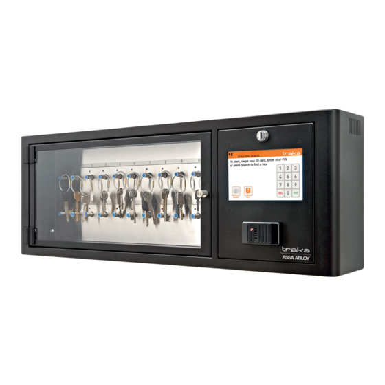
WHAT YOU SHOULD HAVE Once you receive your Traka Touch system, please open the box and check you have the following… Traka Touch M cabinet Wall Mounting Bracket 2x Override Keys 3x M5 x 8.0 - Socket Button Screws (Traka Part No. FF-5-0030) V5.0 03/08/18... -
Page 10: Tools And Materials Required For Installation
1x Ferrite Core (FF-3-0049) Only required if connecting to a network If you are missing any of the above please contact Traka immediately. NOTE: Traka do not provide wall fixings for your system. Please ensure you source appropriate fixings for the type of wall you are fixing to. - Page 11 NOTE: All dimensions are in mm. Knockout Dimensions NOTE: Traka systems can be quite heavy and therefore need a strong wall to fix to. Fixings are not included and so when selecting the appropriate fixings it is essential they are strong enough to retain the Traka System and not pull out from the wall.
-
Page 12: Installing The System
The Traka Touch M can be mounted directly to the wall, however, it is much easier for installation and maintenance purposes that you mount the provided wall mounting plate to the desired location and secure the Traka Touch M to the plate. - Page 13 Using one of the Master keys, open the control pod by turning the key 90° clockwise. The Control Panel will now lean forward at 90°. You will see two fixing holes which will allow the system to be secured to the wall bracket. Using the supplied M5x8mm fixings, secure the cabinet to the wall bracket via the two fixing holes.
- Page 14 10. The remaining fixing point to secure the system to the mounting plate is located behind the bottom receptor strip. Manually release the door to gain access to the receptor strips by lifting the catch on the lock mechanism. 11. Remove the 2 cover panels by removing the hex screws. 12.
- Page 15 13. A fixing point is located behind the receptor strip. Use the remaining M5x8mm screw to secure the system to the mounting plate. 14. Reconnect and replace the receptor strip and cover panels and close the door. 15. Inside the control compartment of the cabinet is the mains cable. This should be fed out of one of the 20mm knockout holes located on the top and bottom of the system’s outer shell.
- Page 16 16. A network connection may also be required. Use the diagram below to locate the network port in the control panel of the Traka Touch. 17. Feed the network cable out through one of the other 20mm knockouts in the cabinet’s outer shell. 18.
-
Page 17: Connecting The Mains Power
CONNECTING THE MAINS POWER IMPORTANT: The installation of Traka products must be carried out in accordance with any local electrical installation codes/standards that may apply. NOTE: A readily accessible mains disconnection device must be incorporated in the building installation wiring and this device must enable double pole disconnection. NOTE: In the case of a battery being fitted there are two power sources present. - Page 18 Follow the process below to install the surge protection module. The cover on the surge protection module is secured with M4 Torx screws. Remove the screws using a T25 Torx driver and remove the cover. There will be an earth lead connected to the cover that can also be disconnected. NOTE: Ensure the module is not connected to the mains power outlet before removing the cover.
- Page 19 Pass the mains cable from the Traka Power Supply through the cable gland and connect the Live (L), Earth (E) and Neutral (N) wires to the terminal block as labelled, and then tighten the cable gland. Refit the cover. Connect the plug to the mains power outlet. V5.0 03/08/18 TD0034 Page 19 of 30...
- Page 20 V5.0 03/08/18 TD0034 Page 20 of 30 This Document is uncontrolled when printed unless over stamped “CONTROLLED DOCUMENT”...
-
Page 21: Switching On The System
SWITCHING ON THE SYSTEM The system will automatically boot up when the mains is connected. However, if you are powering the system from a backup battery alone, or the system has been switched off with the mains still connected, you can switch the system on following the steps below. -
Page 22: Product Disconnection
PRODUCT DISCONNECTION MAINS DISCONNECTION To completely disconnect the system from the mains follow the steps below: If the product is connected to a non-switched fused spur, remove the fuse from the spur. • • If the product is wired to a plug and connected to a power outlet, disconnect the plug from the power outlet. In the case of a battery being fitted there are two power sources to disconnect before any service or •... -
Page 23: Maintenance
MAINTENANCE This section will take you through certain processes that may be useful when servicing the system or if an area is in need of general maintenance. If at any point you are unsure please contact Traka Technical Support for advice. SWITCHING OFF THE SYSTEM Disconnecting the system directly from the mains could result in data loss and should only be done in an emergency. -
Page 24: Manually Opening The Door
MANUALLY OPENING THE DOOR Insert the Master key into the CAM Lock on the Control Panel and turn the key 90° clockwise. The Control Panel will now lean forward at 90°. Manually release the door by lifting the latch on the mechanical lock. V5.0 03/08/18 TD0034 Page 24 of 30... -
Page 25: Serial Number/Rating Plate Location
SERIAL NUMBER/RATING PLATE LOCATION The Traka Touch Serial Number/Rating Plate can be found in the following location: Insert the Master key into the CAM Lock on the Control Panel and turn the key 90° clockwise The Control Panel will now lean forward at 90°. The Rating plate can be found on the back of the Touch System. -
Page 26: Replacing The Fuse In A Surge Protection Device
REPLACING THE FUSE IN A SURGE PROTECTION DEVICE NOTE: This section only applies to systems installed in the USA and Canada. Each surge protection device is fitted with a ‘slow-blow’ 3A fuse. The fuse specification is: 3A 125V 6.3x32mm Slow Blow •... -
Page 27: Backup Battery
BACKUP BATTERY 9.5.1 BATTERY LOCATION Traka provide a backup battery already connected with every Touch System supplied in the UK. If for any reason you need to connect/disconnect the battery yourself please follow this section and then refer to the connection details below. Insert the Master key into the CAM Lock on the Control Panel and turn the key 90°... - Page 28 NOTE: When you first receive your Traka Touch System the battery cable will already be terminated at the battery end but will NOT be connected to the Traka Touch PCB. The battery connection area is shown below. V5.0 03/08/18 TD0034 Page 28 of 30 This Document is uncontrolled when printed unless over stamped “CONTROLLED DOCUMENT”...
- Page 29 9.5.2 BATTERY CONNECTION DETAILS The battery inside the Traka Touch will already be connected to the battery cable when you receive your system, if however you need to replace a battery or the cable, please reconnect using information below. If you are unsure please contact Traka Technical Support using the details at the end of this document.
- Page 30 10. TECHNICAL SUPPORT If you need to contact Traka/distributor for technical support, please use the contact information below. Telephone: 0845 630 6300 Email: support@traka.com Web: support.traka.com V5.0 03/08/18 TD0034 Page 30 of 30 This Document is uncontrolled when printed unless over stamped “CONTROLLED DOCUMENT”...
Need help?
Do you have a question about the TRAKA TOUCH M and is the answer not in the manual?
Questions and answers