Table of Contents
Advertisement
Quick Links
OxySense
Flow Meter
Users Guide
© Industrial Physics Product Integrity
OxySense
An Industrial Physics Product Integrity Brand
68 Branum Road, Devens, MA 01434. USA
Phone: (978) 772-0970
Website:
www.oxysense.com
Email:
PiSales@industrialphysics.com
Technical Support email:
PiSupport@industrialphysics.com
Document Revised: July, 2020
Information in this document is subject to change without notice. Any reference to a company or
data used as examples herein is fictitious unless otherwise noted. No part of this document may
be reproduced or transmitted in any form or by any means for any purpose without express
written permission.
All other company and product names are the trademarks or registered trademarks
of their respective companies.
All Rights Reserved
Advertisement
Table of Contents

Summary of Contents for OxySense 300446-501
- Page 1 OxySense Flow Meter Users Guide © Industrial Physics Product Integrity OxySense An Industrial Physics Product Integrity Brand 68 Branum Road, Devens, MA 01434. USA Phone: (978) 772-0970 Website: www.oxysense.com Email: PiSales@industrialphysics.com Technical Support email: PiSupport@industrialphysics.com Document Revised: July, 2020 Information in this document is subject to change without notice. Any reference to a company or data used as examples herein is fictitious unless otherwise noted.
- Page 2 Flow Meter User’s Guide Page i Document Revised: July, 2020 Copyright © Industrial Physics Product Integrity 2020 All Rights Reserved. Information in this document is subject to change without notice. Any reference to a company or data used as examples in this document may not be used for any purpose without express written permission is prohibited.
-
Page 3: Table Of Contents
Flow Meter User’s Guide Page ii Table of Contents Introduction ................... 1 Flow Meter Assembly ..............2 Assembly Components................2 Flow Meter..................2 Tube Fittings ..................3 Instructions ..................4 Considerations................8 Flow Rate....................8 Using Pure Oxygen ................8 Technical Support................9 List of Figures Figure 2-1: Flow Meter Assembly (Side View).............. -
Page 4: Introduction
Industrial Physics Product Integrity provides a flow meter for use with the OxySense® Permeation Chamber, an accessory designed for polymer film oxygen transmission rate (OTR) analysis. The reason being: polymer films are flexible. -
Page 5: Flow Meter Assembly
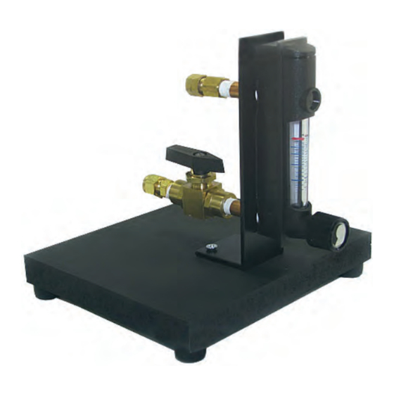
Flow Meter User’s Guide Page 2 of 9 2.0 Flow Meter Assembly 2.1 Assembly Components The flow meter assembly (OxySense P/N: 300446- Gas Out 501) is composed of a flow meter, wooden base, gas-tight tube Flow Meter compression fittings, and Check Valve a brass check valve. -
Page 6: Tube Fittings
Flow Meter User’s Guide Page 3 of 9 2.3 Tube Fittings Outlet Compression Nut The flow meter assembly is shipped with gas- tight compression fittings located at the inlet and outlet. The fittings accommodate 1/4 ⁄ ” inch (6 mm) outer diameter (O.D.) tubing. Tubing should be composed of a non-reactive material such as stainless steel or nylon. -
Page 7: Instructions
Flow Meter User’s Guide Page 4 of 9 3.0 Instructions Connect tubing to the flow meter’s inlet and outlet with the provided Step 1: gas-tight compression fittings. Insert tubing through nuts and ferrules (tubing is not provided). Firmly tighten fittings by turning clockwise using the appropriate size wrenches. - Page 8 Flow Meter User’s Guide Page 5 of 9 Open the check valve on the Open the main valve on the Step 3: Step 4: flow meter turning gas cylinder to begin the flow clockwise. of gas. Set the regulator pressure to 20 psig (140 kpag).
- Page 9 Flow Meter User’s Guide Page 6 of 9 Connect the flow meter outlet to the desired inlet on the permeation Step 7: chamber. If purging the top of the chamber with pure nitrogen, connect to the top inlet. If purging the bottom of the chamber with pure oxygen, connect to the bottom inlet (See Section 4.2 Using Pure Oxygen).
- Page 10 Flow Meter User’s Guide Page 7 of 9 If purging the top of the After purging is complete, Step 10: Step 11: chamber, allow the gas to close permeation flow for at least 60 seconds. chamber inlet and then the If purging the bottom of the outlet valve...
-
Page 11: Considerations
The final OTR result obtained from a test using either atmospheric oxygen (i.e. air) or pure oxygen will be identical. This is because the algorithm employed by OxySense to calculate OTR yields a result that is normalized to the oxygen concentration in the bottom of the chamber. -
Page 12: Technical Support
Flow Meter User’s Guide Page 9 of 9 5.0 Technical Support For technical support, contact Industrial Physics Product Integrity PiSupport@IndustrialPhysics.com Email: Phone: +1 (978) 772.0970 Copyright © Industrial Physics Product Integrity 2020...
Need help?
Do you have a question about the 300446-501 and is the answer not in the manual?
Questions and answers