
Related Manuals for Tektronix 544


Summary of Contents for Tektronix 544
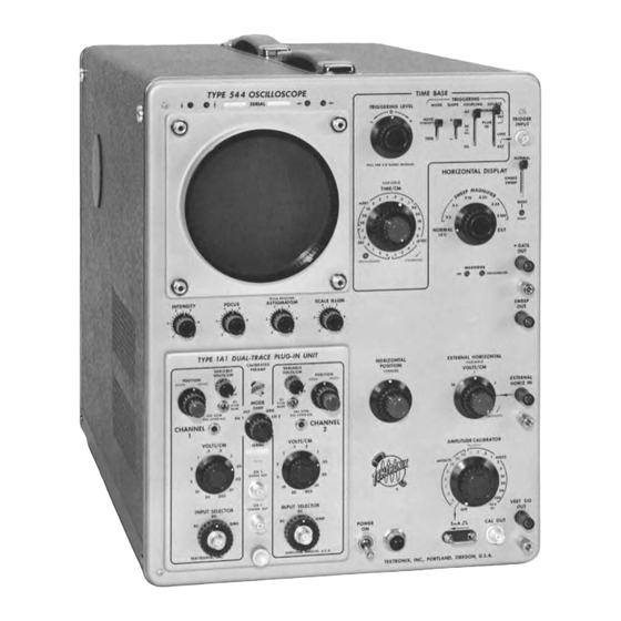
- Page 1 I V I A I N I UAL Serial Number 54 4 ty p e OSCILLOSCOPE Tektronix, Inc. S.W. M illikan W ay • P. O. Box 500 • Beaverton, Oregon 97005 • Phone 644-0161 • Cables: Tektronix 070-418...
- Page 2 WARRANTY All Tektronix instruments are warranted against defective materials and workman ship for one year. Tektronix transformers, manufactured in our own plant, are w ar ranted for the life of the instrument. Any questions with respect to the w ar...
- Page 3 A list of abbreviations and symbols used in this manual will be found on page 6-1. Change information, if any, is located at the rear of the manual. Type 544...
- Page 4 Type 5 4 4...
- Page 5 * *M u ltip le -tra c e p lu g -in units. ♦Special feature p lu g -in un it. See you r Tektronix catalog fo r more inform ation on an y o f these plu s ,n un,fSl...
- Page 6 + 2 0 volts with a risetime of 0.5 Signal ^.sec or faster. ♦W ith line frequencies ether than 5 0 -6 0 cycles, a special fa n m o d ifi Requirements cation is required; contact your local Tektronix Fiold Representative. 1 -2...
-
Page 7: Triggering Level
FUNCTIONS OF CONTROLS AND DISPLAY positions connect the time-base circuitry to CONNECTORS the horizontal deflection system of the Type 544. The SWEEP MAGNIFIER posi TRIGGERING Selects the amplitude point on the trig tions expand the display horizontally by LEVEL gering signal where sweep-triggering oc... - Page 8 The PLUG-IN position is for plug-in units that will supply a single-channel triggering signal through pin 5 of the inter connecting plug, such as the Tektronix Type 1A1 Dual-Trace Selecting Trigger Mode Plug-In Unit. This position is useful when operating the plug...
- Page 9 Operating Instructions— Type 544/R M 544 Fig. 2-1. Effects o f the TRIGGERING LEVEL and SLOPE controls. ®...
- Page 10 To avoid this, use the single-sweep feature of the Type 544. To use single sweep, first make sure the trigger circuit will trigger on the event you wish to display.
- Page 11 Operating Instructions— Type 544/R M 544 W hite w ith green stripes W hite w ith black stripes Y ellow w ith brow n stripes (solid black) operation, move fan lead. 108 to 122 volt operation Fig. 2-3. Transformer connections fo r 108 to 244 volts, 50 to 60 Fig.
- Page 12 NOTES...
- Page 13 NORMAL XI position. on the oscillator transformer supply voltages to the high- Fig. 3-1 is a simplified block diagram showing the Type 544 voltage rectifiers. operating in this mode. The functions of the various blocks in Fig.
- Page 14 Circuit Description— Type 5 4 4 /R M 5 4 4 Fig. 3-1. Type 544 sim p lifie d block diagram .
- Page 15 - f 100-volt supply is required to supply current to a supply increases due to increased line voltage of some other series string of filaments at all times. When the Type 544 is cause, the voltage increase appears on the cathodes of V624 first turned on, relay K601 contacts are open and all the and, through the tap on R616, on the grid of V624B.
- Page 16 Type 544 at the top cathode contact-bias compensating diode. rear of the plug-in compartment. When the plug-in unit is removed, the sensing switch connects a resistive load in place of the series-filament string.
- Page 17 V800 and the An input binding post on the rear panel of the Type 544 amplitude of the 50-kc oscillations. R840 provides a means of provides an input for externally modulating the crt cathode.
- Page 18 Circuit Description— Type 5 4 4 /R M 5 4 4 emitter circuit. Zener diode D1018 sets the operating points Trigger Generator. The input to the sweep trigger circuit of the termination transistors on both ends of the delay line. (see Sweep Trigger schematic) is selected by SOURCE switch The rc networks in the collectors of Q1014, Q1024, Q1144, SW201 from the trigger-pickoff circuit in the vertical ampli...
- Page 19 Q275 and disables the automatic stability feature the holdoff multivibrator to switch, and V345B biases sweep of the Type 544. When the triggering MODE switch is in tunnel diode D285 to the ready point as previously explained. the AUTO STABILITY position, the sweep generator free tuns Since Q284 and V345A are both cut off, the positive voltage if no trigger pulses are received from the trigger generator.
- Page 20 Q534 along with dc-positioning voltages from the horizontal positioning controls. The composite signal output The amplitude calibrator in the Type 544 is a 1-kc square- of Q534 is applied to emitter follower Q543, and from that wave generator (see Amplitude Calibrator schematic) that transistor to the paraphase amplifier.
- Page 21 Circuit Description— Type 544/R M 544 Square-W ave Generator. The square-wave generator is to +100 volts. When the signal from the V945 plate goes an astable multivibrator direct-coupled to a cathode follower. negative, V935B is cut off and the cathode voltage goes to V935A and V945 are the multivibrator tubes, with the screen ground potential.
- Page 22 NOTES...
- Page 23 Exterior. Loose dust accumulating on the outside of the Type 544 can be removed with a cloth or small paint brush. The paint brush is particularly useful for dislodging dust on and around the front-panel controls. Stubborn dirt con be re...
- Page 24 General Information cess as close to the joint as possible. Remove all wire clippings from the chassis. Many components in the Type 544 are mounted in a par ticular way to reduce stray inductance and capacitance. Tubes and Transistors While removal or replacement procedures for most parts...
- Page 25 Maintenance— Type 544/R M 544 7. Grasp the face of the crt with the right hand. Push the crt carefully towards the front of the Type 544 Eyebrow with the left hand. Be careful not to bend the neck pins. Remove the crt through the front of the oscillo...
- Page 26 2. Crt Circuit (including the High-Voltage Power Supply) Check the settings of all controls on the Type 544 and the vertical plug-in preamplifier unit. A control set to the wrong 3.
- Page 27 (4) VOM (Volt-Ohm-Milliammeter) DC sensitivity of at least Introduction 20,000 ohms per volt. The Type 544 Oscilloscope is a stable instrument which will Calibrated for an accuracy of at least 1% at — 150, provide many hours of trouble-free operation. However, to + 100, +225, and +350 volts;...
- Page 28 Calibration— Type 5 4 4 /R M 5 4 4 ASTIGMATISM As is 4. Lay the oscilloscope on its left side for access to the bot tom of the instrument, (and later in the procedure for SCALE ILLUM access to the — 150 VOLTS control). TRIGGERING LEVEL ccw, knob pushed in 5.
- Page 29 Calibration— Type 544/R M 544 GEOMETRY HIGH VOLTAGE X10 CAL Corner Rail Removed REGIS ■ R861 R840 R544 g5 66 R569 X I 0 0 CAL RS6S SWEEP C290C GAIN LENGTH R S I R325 R 5 1 9 C290B (.S i/O...
- Page 30 C alibration— Type 544/R M 544 4. Check High Voltage Regulation— Crt Circuit e. Reset the autotronsformer for 115 volts output (or de sign-center voltage for which the instrument is wired). a. With the VOM connected to the high voltage test point, use the meter to monitor the voltage at this f.
- Page 31 Calibration— Type 544/R M 544 NOTE 9. Adjust VERT DC BAL (Vertical Am plifier Dc Balance) R1004— Vertical Am plifier + 50 volts indicates a nominal duty factor of 0.5. If the voltage is not within -|-45 to + 5 5 volts, try a.
- Page 32 Calibration— Type 544/R M 544 h. Set the Type TU-7 Test Function switch to Common TABLE 5-4 Mode. INTENSITY i. Adjust the VERT DC BAL control R1044 (see Fig. 5-4) FOCUS to position the trace to the center of the graticule.
- Page 33 Calibration— Type 544/R M 544 14. Adjust INT TRIG DC LEVEL (Internal Trigger DC counterclockwise. Return the TRIGGER LEVEL CEN Level) R209— Sweep Trigger TERING R225 control to its fully clockwise position and repeat step (h). a. Set the AMPLITUDE CALIBRATOR switch to .5 VOLTS.
-
Page 34: Variable (Time/Cm)
Calibration— Type 544/R M 544 b. Apply 100-ju.sec, 1-msec and 5-msec time markers f. Disconnect the VOM or 10X probe. from the time-mark generator through a coaxial cable g. Disconnect the coax cables, 'T' connector, and set to the TU-7 Ext Input connector. - Page 35 Calibration— Type 544/R M 544 NOTE 21. Check X50, X20, X5 and X2 Sweep-Rate Timing Accuracy The following hints should help you to obtain the Using Table 5-6 as a guide, check the X50, X20, X5 and best results in checking and adjusting the time-base X2 magnified sweep-rate timing.
- Page 36 Calibration — T y p e 5 4 4 / R M 5 4 4 23. Adjust SWEEP LENGTH R325 b. Set the TIME/CM switch to 1 ^SEC. a. Set the time-mark generator for 100-^.sec and 1-msec c. Set the TU-7 Variable control so the markers are time-marker output.
- Page 37 Type 544/R M 544 C a lib r a tio n — b. Check that the TIME/CM switch is set to .1 ,uSEC. NOTE c. Set the TU-7 Variable control so the display is about If best timing cannot be obtained and the sweep seems too long, readjust C572 slightly to reduce the 4 cm in amplitude.
- Page 38 Calibration— Type 544/R M 544 d. Set the HORIZONTAL DISPLAY switch to NORMAL. MAL and positioning the start o f the sweep to coin cide with the 4.5-cm point on the graticule. Then set e. Using the HORIZONTAL POSITION and VERNILR...
- Page 39 Calibration— Type 544/R M 544 The remaining front-panel controls of the oscilloscope b. Connect a single binding post adapter (item 9) to the and TU-7 are already set to the positions listed in TU-7 Ext Input connector. Table 5-9. c. Connect an interconnecting lead (item 12) from the...
- Page 40 Calibration— Type 5 4 4 /R M 5 4 4 (a ) C alibrator wa veform display. Fig. 5 -10. Distortion obtained w hen C503C is misadjusted. IR 510 and C 524 are properly adjusted.) b. Check that the display is 5 cm in amplitude. Toler ance is ±...
- Page 41 Calibration— Type 544/R M 544 TABLE 5 -1 0 Oscilloscope INTENSITY FOCUS ASTIGMATISM SCALE ILLUM TRIGGERING LEVEL Knob pushed in Single Sweep Switch NORMAL HORIZONTAL POSITION About — 45° from center - — VERNIER (HORIZONTAL Centered POSITION) Type TU-7 (a ) Norm al w aveform ;...
- Page 42 Calibration— Type 544/R M 544 TABLE 5-11 Vertical Am plifier High-Frequency Adjustments Cl 1 26 For Location Approximate Adjustment See Fig. Area Affected* L1157 5-12b 0 to 100 nsec, adjust 1 0 6 for minimum wrinkles. Cl 029“ 5-12a Termination bump at...
- Page 43 If a part you have ordered has been replaced with a new or improved part, your local Tektronix Field Office will contact you concerning any change in part number. ABBREVIATIONS AND SYMBOLS...
- Page 44 Parts List— Type 544 FRONT 6 - 2...
- Page 45 Parts List— Type 544 FRONT SERIAL/MODEL NO. REF. PART NO. DESCRIPTION EFF. DISC. 378-0541 -00 FILTER, lens, neon light PANEL, front 333-0780-00 Mounting Hardware: (not included) 213-0088-00 SCREW, thread forming, 4-40 x y4 inch PHS phillips PLATE, front sub-panel 387-0865-00...
- Page 46 Parts List— Type 5 4 4 FRONT (Cont'd) SERIAL/MODEL NO. REF. DESCRIPTION PART NO. EFF. DISC. 366-0117-00 KNOB, HORIZONTAL DISPLAY, large charcoal Includes: 213-0004-00 SCREW, set, 6-32 x inch HSS 262-0608-00 SWITCH, HORIZONTAL DISPLAY, wired Includes: 260-0576-00 SWITCH, unwired Mounting Hardware: (not included) 210-0413-00 NUT, hex, 3 /8-3 2 x y 2 inch 210-0840-00...
- Page 47 Parts List— Type 544 FRONT (Conf’d J SERIAL/MODEL NO. REF. DESCRIPTION PART NO. EFF. DISC. POST, binding 129-0064-00 Mounting Hardware For Each: (not included) 358-0181-00 BUSHING, nylon, charcoal NUT, keps, 6-32 x 5 / ^ inch 210-0457-00 129-0020-00 POST, binding assembly...
- Page 48 Parts List— Type 544 FRONT (Conf'c/J SERIAL/MODEL NO. REF. PART NO. DESCRIPTION EFF. DISC. 131-0274-00 CONNECTOR, chassis mounted, BNC BOLT, current loop 214-0335-00 Mounting Hardware: (not included) 210-0593-00 NUT, current loop, hex, 5-40 x y4 inch SPACER, current loop 361-0059-00...
- Page 49 Parts List— Type 544 FRONT (Cont'dl SERIAL/MODEL NO. REF. DESCRIPTION PART NO. EFF. DISC. 366-0254-00 KNOB, ASTIGMATISM, small charcoal Includes: SCREW, set, 6-32 x 3 / 1 (S inch HSS 213-0004-00 Mounting Hardware For Pot: 210-0590-00 NUT, hex, %-32 x 7 / u inch WASHER, .390 ID x 9 / u inch OD...
- Page 50 Parts List— Type 5 4 4 I ff , SERIAL/MODEL NO. PART NO DESCRIPTION IFF. DISC 136-0035-00 SOCKET, graticule lamp Mounting Hardware For Each: (not included) ■ 211-0534-00 SCREW, 6-32 x */,„ inch PHS with lockwashcr 210-0803-00 WASHER, 6L x % inch 210-0457-00 NUT, kops, 6-32 x s /w inch 166-0328 00...
- Page 51 Parts List— Type 544 RIGHT SIDE SERI A l/M O D E L NO. • DESCRIPTION PART DISC ANGLE, frame, top right 122-0019-00 Mounting Hardware: (not included) SCREW, 6-32 x % inch FHS phillips 211-0559-00 NUT, kcps, 6-32 x s /u inch...
- Page 52 Parts List— Type 544 RIGHT SIDE (Conf'dJ SERIAL/MODEL NO. REF. PART NO. DESCRIPTION EFF. DISC. Mounting Hardware For Each 20 W att Resistor: SCREW, 8-32x1% inches Fil HS 212-0037-00 WASHER, resistor centering 210-0808-00 NUT, hex, resistor mounting 210-0462-00 SCREW, 8-32 x %l4 inch BHS...
- Page 53 Parts List— Type 544 RIGHT SIDE (Conf’dJ SERIAL/MODEL NO. REF. DESCRIPTION PART NO. DISC. EFF. 337-0574-00 SHIELD, calibrator switch Mounting Hardware: (not included) 211-0507-00 SCREW, 6-32 x 5 /,6 inch BHS 210-0803-00 WASHER, 6Lx % inch 210- 0457-00 NUT, keps, 6-32 x 5 / u inch...
- Page 54 Parts List— Type 5 4 4 LEFT SIDE 6 - 1 2...
- Page 55 Parts List— Type 544 LEFT SIDE SERIAL/MODEL NO. REF. DESCRIPTION PART NO. EFF. DISC. ANGLE, rail, top left 122-0109-00 Mounting Hardware: (not included) SCREW, 6-32 x inch FHS phillips 211-0559-00 NUT, keps, 6-32 x s /u inch 210-0457-00 BRACKET, support...
- Page 56 Parts List— Type 5 4 4 LEFT SIDE (Coni'd) SERIAL/MODEL NO. REF. DESCRIPTION PART NO. EFF. DISC. COVER, pot 200-0269-00 CLAMP, cable, size “ D” , delrin snap 343-0089-00 CLAMP, cable, % inch 343-0013-00 Mounting Hardware: (not included) NUT, keps, 8 -3 2 x n/ 32 inch 210-0458-00 WASHER, "D "...
- Page 57 Parts List— Type 544 BOTTOM SERIAL/MODEL NO PART NO. DESCRIPTION EFF. OISC. 122-0108-00 ANGLE, rail, bottom Mounting Hardware For Each: (not included) 212-0039-00 SCREW, 6-32 x ’/• inch THS phiilips 210-0458-00 NUT, keps, 8 -3 2 x n/ j j inch...
- Page 58 Parts List— Type 544 REAR 6-16...
- Page 59 Parts List— Type 544 REAR SERIAL/MODEL NO. REF. DESCRIPTION PART NO. EFF. DISC. CONNECTOR, chassis mounted, 1 contact, BNC 131-0106-00 Mounting Hardware: (not included) 210-0413-00 NUT, hex, %-32 x inch '/ 2 210-0255-00 LUG, solder 387-0868-00 PLATE, rear overlay Mounting Hardware: (not included)
- Page 60 Part* List— Type 544 VERTICAL AMPLIFIER CHASSIS S IR IA t/M O D IL NO. DISCRIPTION PART NO DISC. CHASSIS, vertical amplifier 441 -0473-00 CHASSIS, vertical amplifier 441-0473-01 Mounting Hardware: (not included) SCREW, 8-32 x */.« inch BHS 212-0004-00 WASHER, 8S x */, inch...
- Page 61 Parts List— Type 544 VERTICAL AMPLIFIER CHASSIS (Con fd ) SERIAL/MODEL NO. REF. PART NO. DESCRIPTION EFF. DISC. 136-0015-00 SOCKET, STM9G Mounting Hardware For Each: (not included) 213-0044-00 SCREW, thread cutting, 5 -3 2 x 3 / )(S inch PHS phillips...
- Page 62 Parts List— Type 544 VERTICAL AMPLIFIER CHASSIS (Cont'dJ SERIAL/MODEL NO. REF. DESCRIPTION PART NO. EFF. DISC. ROD, aluminum 385-0024-00 Mounting Hardware For Each: (not included) SCREW, 6-32 x 5 /,6 inch BHS 211-0507-00 LUG, solder, SE6 210-0202-00 LUG, solder, SE4...
- Page 63 Parts List— Type 544 SWEEP CHASSIS SERIAL/MODEL NO. PART N O . DESCRIPTION EFP. DISC. Mounting Hardware For Each Pol: • 210-0413-00 NUT, hex, Vs-32 x '/j inch 210-0840-00 WASHER, .390 ID x */u inch OD 337-0588-00 SHIELD, sweep generator...
- Page 64 Parts List— Type 544 SWEEP CHASSIS (Cont'dj SERIAL/MODEL NO. REF. PART NO. DESCRIPTION EFF. DISC. STRIP, ceramic, 7 / ](S inch x 9 notches 124-0157-00 Each Includes: STUD, nylon 355-0082-00 Mounting Hardware For Each: (not included) SPACER, nylon, n/ 32 inch...
- Page 65 Parts List— Type 544 SWEEP CHASSIS (Conf'c/J SERIAL/MODEL NO. REF. DESCRIPTION PART NO. EFE. DISC. ROD, nylon 385-0033-00 Mounting Hardware: (not included) 211-0507-00 SCREW, 6-32 x 5 / u inch BHS 136-0095-00 SOCKET, 4 pin transistor SOCKET, 3 pin transistor...
- Page 66 Parts List— Type 5 4 4 HIGH VOLTAGE CHASSIS 6-24 ©...
- Page 67 Parts List— Type 544 HIGH VOLTAGE CHASSIS SERIAL/MODEL NO. REF. DESCRIPTION PART NO. EFF. DISC. GROMMET, snap-in 348-0031-00 GROMMET, y inch 348-0005-00 STRIP, ceramic, 3 /4 inch x 7 notches 124-0089-00 Each Includes: STUD, nylon 355-0046-00 Mounting Hardware For Each: (not included) SPACER, nylon, .156 inch...
- Page 68 Parts List— Type 544 HIGH VOLTAGE CHASSIS (Conf'e/J SERIAL/MODEL NO. REF. DESCRIPTION PART NO. EFF. DISC. SLEEVE, high voltage anode lead 166-0357-00 SLEEVE, high voltage 166-0319-00 HOUSING, high voltage 380-0048-00 Mounting Hardware: (not included) SCREW, 6-32 x inch BHS 211-0507-00...
- Page 69 Parts List— Type 544 HIGH VOLTAGE CHASSIS (Cont'd) SERIAL/MODEL NO. REF. DESCRIPTION PART NO. DISC. EFF. CABLE HARNESS, focus and intensity 179-0769-00 392-0147-00 BOARD, high voltage, assembly Includes: 124-0162-00 STRIP, ceramic, 7 / 1 6 inch x 4 notches Includes:...
- Page 70 Parts list— Type 5 4 4 POWER CHASSIS SERI A L /M O D E l NO ( IF PART NO. DESCRIPTION DISC 441-0478-00 CHASSIS, power Mounting Hardwares (not included) SCREW, 8-32 x inch FHS phillips 212-0040-00 210-0458 00 NUT, keps, 8-32 x n/ j} inch 212-0001-00 SCREW, 8-32 x inch BHS...
- Page 71 Parts List— Type 544 POWER CHASSIS (Cont'd) SERIAL/MODEL NO. REF. DESCRIPTION PART NO. EFF. DISC. 348-0004-00 GROMMET, 3 /„ inch COVER, capacitor 200-0560-00 200-0259-00 COVER, capacitor GROMMET, y2 inch 348-0005-00 348-0003-00 GROMMET, y4 inch Mounting Hardware For Pot: 210-0444-00 NUT, hex, %-32 x '/2 x 5 /8 inch 210-0840-00 WASHER, .390 ID x...
- Page 72 Parts List— Type 544 POWER CHASSIS (Cont'd) SERIAL/MODEL NO. REF. DESCRIPTION PART NO. EFF. DISC. Mounting Hardware For Pot NUT, hex, 3 /8-32 x '/2 inch 210-0444-00 WASHER, .390 \D x 9 / u inch OD 210-0840-00 LOCKWASHER, internal, 3 /8...
- Page 73 Parts List— Type 544 CABINET SERIAL/MODEL NO. REF. d e s c r ip t io n PART NO. EFF. DISC. PLATE, cabinet side, left 387-0761-00 Includes: PLUG, steel 134-0028-00 LATCH, quarter turn, assembly 214-0361-00 Each Consisting Of: PIN, securing,index...
- Page 74 Parts List— Type 544 ACCESSORIES SERIAL/MODEL NO. REF. DESCRIPTION PART NO. EFF. DISC. 010-0129-00 PROBE, package, P6008 161-0010-00 CORD, power ADAPTER, 3 to 2 wire 103-0013-00 387-0918-00 PLATE, protector 378-0545-00 FILTER, light, smoke gray (installed) 378-0567-00 FILTER, light, smoke gray (installed)
- Page 75 Parts List— Type 544 ELECTRICAL PARTS Values are fixed unless marked Variable. Tektronix Ckt. No. Part No. Description S /N Range Bulbs B289 150-030 Neon, NE-2V READY B290W 150-030 Neon, NE-2V UNCALIBRATED B294 150-027 Neon, NE-23 B520 150-030 Neon, NE-2V...
- Page 76 Parts List— Type 544 Capactiors (Cont'dj Tektronix S /N Range Desc ription Part No. Ckt. No. 500 v C290D 281-574 82 pf 0.001 pf \ C290E \ 0.01 C290F Timing Series C290G ) *295-073 C290H \ C290J / 500 v 283-001 0.005...
- Page 77 Parts List— Type 544 Capacitors (Conf'c/J Tektronix Ckt. No. Part No. Description S /N Range 3-12 pf C557D 281-009 8-50 pf C557F 281-013 8-50 pf C557H 281-013 C557J Use 281-549 68 pf 500 v C557K 281-013 8-50 pf C557L 281-623...
- Page 78 — Type 5 4 4 P a r ts L is t Capactiors fCont'dJ Tektronix Description Ckt. No. Part No. S /N Range 2 x 40 250 v C771 *290-229 C772 283-002 0.01 /if 500 v C773A ) 4 0 /if )
- Page 79 Parts List— Type 544 Capactiors (Cont'c/J Tektronix Ckt. Mo. Part No. Description S /N Range 500 v Cl 031 281-572 6.8 pf 200 v 283-067 0.001 juf Cl 035 200 v Cl 038 283-067 0.001 juf Cl 042 281-572 6.8 pf 500 v 0.001 fxi...
- Page 80 Parts List— Type 544 Diodes (Cont'dJ Tektronix Description S /N Range Part No. Ckt. No. Silicon Tek Spec D329 *152-061 Tek Sp ;c D332 *152-061 Silicon D347 152-141 Silicon 1N3605 D362 152-141 Silicon 1N36 1 5 D363 152-141 Silicon 1N36I5...
- Page 81 Parts List— Type 544 Inductors f C ont'd) Tektronix Part No. Description S/N Range Ckt. No. 0.2 /xh LI 030 *108-264 LI 040 *108-264 0.2 /xh LI 051 *108-260 0.1 /xh 1.2 /xh (on a 6 2 L 2 '/2 w 5% resistor)
- Page 82 Parts List— Type 544 Transistors (Cont'd) Tektronix Ckt. No. Part No. Description S /N Range Q1124+ *153-526 Q1134++ *153-524 Q1144 *153-527 Matched pair Q1154 *151-127 Selected from 2N2369 Q1163 Selected from 2N2369 Q1173 *151-127 Resistors Resistors are fixed, composition, ± 1 0 % unless otherwise indicated.
- Page 83 Parts List— Type 544 Resistors (Cont'dj Tektronix Ckt. No. Part No. Description S /N Range 'A w R269 3 0 2 -1 0 3 1 0 k R271 51 k 3 0 3 -5 1 3 ’ A w R275...
- Page 84 Parts List— Type 5 4 4 Resistors (Cont'd) Tektronix Ckt. No. Description S /N Range Part No. R324 303-163 R325 SWEEP LENGTH 311-011 R326 305-393 39 k y2 w R328 302-102 y2 v/ R329 302-562 5.6 k R330A 301-155 1.5 meg...
- Page 85 Parts List— Type 544 Resistors C o n t ' d ) T e k t r o n ix Ckt. No. Part No. Description S /N Range R394 316-101 1000 y * w 307-106 R397 4 .7 a 'A w...
- Page 86 Parts List— Type 5 4 4 Resistors ( C o n t'd j Tektronix Ckt. No. Part No. Description S /N Range R557H 301-122 1.2 k y2 w R557J 301-361 360 n R557K 323-122 182 0 Prec R557L 301-750 75 0...
- Page 87 Parts List— Type 544 Resistors ( C o n t'd l T e k t r o n ix Ckt. No. Part No. Description S /N Range R615 324-369 68.1 k Prec R616 311-015 -1 5 0 VOLTS R617 324-356 49.9 k...
- Page 88 Parts List— Type 5 4 4 Resistors (C o n t'd ) Tektronix Ckt. No. Part No. Description S /N Range 302-225 2.2 meg R689 302-155 1.5 meg R693 R694 47 k 302-473 R697 302-824 820 k R698 302-274 270 k...
- Page 89 Parts List— Type 544 Resistors (Coni'd) Tektronix Ckt. No. Part No. Description S /N Range R778t 311-407 2 x lO Q TRACE ROTATION R802 306-271 270 a R803 306-563 56 k R806 302-104 100 k R807 301-432 4.3 k Vs W...
- Page 90 Parts List— Type 544 Resistors (Cont'dj Tektronix Ckt. No. Part No. Description S /N Range 302-221 R941 220 o CAL AMPL R943 311-141 R944 302-100 i o n R945 308-268 22 k X470-up 315-0682-00 6.8 k R948 V i *...
- Page 91 Parts List— Type 544 Resistors ( C o n t'd ) T e k t r o n ix Ckt. No. Part No. Description Range 3 1 5 -5 1 2 R1041 5.1 k Prec R1042 3 2 2 -0 9 2 8 8 .7 Q...
- Page 92 Parts List— Type 544 Switches Tektronix Ckt. No. Part No. Desc ription S /N Range Unwired Wired SOURCE SW201 260-495\ Lever SW205 260-494 Lever COUPLING TDir'r'CDikir' SLOPE TRIGGERING 260-5421 *262-607 Lever SW210 Lever MODE SW375 260-493/ 311-426 PULL FOR X I0 RANGE INCREASE...
- Page 93 Parts List— Type 544 Electron Tubes (Cont'd) Tektronix Ckt. No. Part No. Description S /N Range V677 154-056 6080 V684 12AX7 154-043 V694 154-022 6AU6 V707 154-056 6080 V724 154-022 6AU6 V737 154-202 6CW5 154-187 V764 6DJ8 154-021 6AU5 V800...
- Page 94 Voltage and waveform measurements may vary between instruments due to normal component tolerances. Plug-in unit that was used in the Type 544 is a Type TU-7 Test Unit. Front-panel controls and other conditions that apply to all schematic diagrams are as follows: Input S ig n a l..
- Page 95 T Y P E . OSCILLOSCOPE...
- Page 96 c m d 3fe4 BLOCK DIAGRAM...
- Page 97 T 8 0 1 T R A N S F O R M E R D E T A IL S CRT CIRCUIT W A V E F O R M AND DYNAMIC VOLTAGE READINGS were obtained under th e f o l l o w i n g conditions: IN T E N S IT Y .......
- Page 98 + 2 -2 5 V U N P E G (l T801 TRANSFORMER DETAILS + 3> 2S»V + Int. U KIR EG + 4 9 0 R 8 0 2 IOOV/CM 2 7 0 + 190 IO> SEC./C.M C 8 0 2 _ L + *°M-i J-- + 3 5 0 V C 8 2 5...
- Page 99 C -M O S fe5 C R T CIRCUIT <§>...
- Page 100 POWER SUPPLY VOLTAGE READINGS WERE OBTAINED under the following conditions: LINE V O LTA G E .......... 115 VAC (or Design Center) INPUT SIGNAL .......... None TRIGGER INPUT S ig n a l......None TRIGGERING LEVEL........ccw TRIGGERING M O D E ......... • TRIG TRIGGERING SOURCE.......
- Page 101 FOCUS $ INTENSITY CHASSIS V677 V 6 6 4 - €080 €BYe M RH H E A T E R W I R I N G D I A G R A M T Y P E 5 4 4 O S C I L L O S C O P E...
- Page 102 R7SO K . 601-6 P O W E R . S U P P L Y < } >...
- Page 103 VERTICAL AMPLIFIER QUIESCENT VOLTAGE READINGS were obtained under the following conditions: Oscilloscope: PO W E R ............ Type TU-7: INPUT S IG N A L ........None VERTICAL POSITION ......Centered* TEST F U N C T IO N ........COM MON MODE *lf a letter-series or ‘...
- Page 104 +xzsv NO CONNECTION _L cioza " " .oos Rll4t © e.i QNAA + 73 RM 4Z + 83 + 3' C 1 I-4Z .001 RII84- REFERENCE. DRAWINGS R114.4 330K. e©o SWEEP TRIGGER + 298 < S > P L U G - I N C O N N E C T O R LI 144 V U Q A A «...
- Page 105 4-IOO V J T ' C l 14-1 .oos + 9 3 L llfe O J|l V E R T IC A L S IG N A L - T0€> O O K J 2 € > 4 > <§> VERTICAL a m p l if ie r...
- Page 106 SWEEP TRIGGER WAVEFORMS AND VOLTAGE READINGS were obtained under the fol lowing conditions: TIME BASE TRIGGERING: M O D E ..........TRIG SLO PE..........COUPLING ........SOURCE ..........HORIZONTAL DISPLAY......NORMAL PO W E R ............ON WAVEFORM Conditions — TRIGGER INPUT Signal .
- Page 107 + IOOV ' 3 > P L U G - I N C O N N E C T O R T Y P E 6 4 4 O S C I L L O S C O P E...
- Page 108 JR249 » IOO C 2 4 9 + IOOV |_ _ (DE-C)_______ OtCOUPLING cm d SWE.E.P TRIGG ER <^>...
- Page 109 SWEEP GENERATOR WAVEFORMS AND VOLTAGE READINGS were obtained under the fol lowing conditions: TIME BASE TRIGGERING LEVEL......+ 45°; pushed in TRIGGERING: SLO PE..........COUPLING ........AC SOURCE ..........EXT BRIGHTNESS......... cw . .1 mSEC TIME/CM ..........VARIABLE (TIME/CM) ......
- Page 110 O.ZV/CM 5 V /C M SEE PARTS LIST FOR EARLIER VALUES AN D SERIAL NUMBER RANGES OF PARTS MARKED WITH BLUE OUTLINE. P A R T S L IS T F ? R „ “ R 3 € » e £ SEMICO NDUCTOR T V P fc b 1 K >...
- Page 111 M R I4 S W E E P G E N E R A T O R < § >...
-
Page 112: Table Of Contents
HORIZONTAL AMPLIFIER WAVEFORM AND VOLTAGE READINGS were obtained under the fol lowing conditions: TIME BASE TRIGGERING LEVEL ......+ 4 5 ° ; pushed in TRIGGERING: M O D E ..........TRIG SLOPE..........COUPLING ........SOURCE ..........TIME/CM ..........1 mSEC/CM VARIABLE (TIME/CM) ...... - Page 113 &WS30 RANGES O f PARTS MARKED w it h b lu e o u t l in e I---------------------------- XIOO X IO o-------- C S O S A . C S O S C 2 . 1 ' 7 - 4 6 1 ------- °...
-
Page 115: Waveform Conditions
SYNC AMP. WAVEFORM AND VOLTAGE READINGS were obtained under the fol lowing conditions: HORIZONTAL DISPLAY......NORMAL TIME BASE . None TRIGGER INPUT S ig n a l..... . cw TRIGGERING LEVEL......EXT TRIGGERING SOURCE......50 / T IM E /C M .......... - Page 116 + IO O V ALTERNATE. TRACE SYNC FROM PULSE PIN & ,VS4S <S > R E F E R E N C E D R A W I N G S « P O W E R S U P P L Y $ N E A T E R W IR IN G D IA G C R T C IR C U IT v e r t i c a l a m p l i f i e r...
- Page 117 5 > s > <...
- Page 118 CALIBRATOR WAVEFORM AND DYNAMIC VOLTAGE READINGS were obtained under the following conditions: AMPLITUDE CALIBRATOR ......10 Volts P O W E R ............ON Also see IMPORTANT note on Block Diagram.
- Page 119 <$>...
- Page 120 MANUAL CHANGE INFORMATION At Tektronix, we continually strive to keep up with latest electronic developments by adding circuit and component improvements to our instruments as soon as they are developed and tested. Sometimes, due to printing and shipping require ments, we can’t get these changes immediately into printed manuals.
- Page 121 TYPE 5kk TENT SN 6kO PARTS I S T CORRECTION CHANGE > ,C ,D 1 5 2 -0 0 6 6 -0 0 S l i e o n A ,: 6 7 2 M 9975/666...
- Page 122 ^bh/m^,kh TENT SN 600 T Y P E PARTS LIST CORRECTION CHANGE l / 2 W 3 0 2 -0 8 2 3 -0 0 SCHEMATIC CORRECTION V & G 2 P A R T IA L C R T M 1 0 A 5 9 /9 6 6...
- Page 123 TYPE 5 W R M 5 ^ TENT SN 620 PARTS LIST CORRECTION CHANGE TO: C1035, CIO C1048, C 1069 0078-00 0.001 nF 1 KV C1071, CIO C113, C1132 0985/666...
- Page 124 Page 1 o f 2 Type , and ALL RM'3 TEXT COLLECTION CALIBRATION R e p la c e s s t e p s 12 and 13 c n ly o f 5^ • R e p la c e s s t e p s 1 2 , 1 3 , 17 and 18 o f 5^6/RM5^6, 5^7/RM5^7- ALL n o t e s in ( ) r e f e r t o MAIN TIME BASE ( A d ju st A TRIGGERING LEVEL CENTERING R225 (R 25) and A TRIGGER...
- Page 125 Page 2 o f 2 T r ig g e r in g Mode A utom atic S lop e C oupling Source I n t e r n a l S e t th e TRIGGER SENS (R io ) t o m idrange. R o ta te TRIGGER LEVEL CENTERING R225 (R25) f u l l y c o u n te r c lo c k w is e .
- Page 126 TYPE ^ h k TENT S/N 510 TYPE RM PARTS LIST CORRECTION CHANGE TO: C 1019 2 8 1 - 0 5 0 5 - 0 0 12 pF C e r 5 0 0 M 1 0 5 5 7 / 1 6 6...
Need help?
Do you have a question about the 544 and is the answer not in the manual?
Questions and answers