Advertisement
Quick Links
Advertisement

Related Manuals for Zeta Alarm Systems Zeta Beam

Summary of Contents for Zeta Alarm Systems Zeta Beam
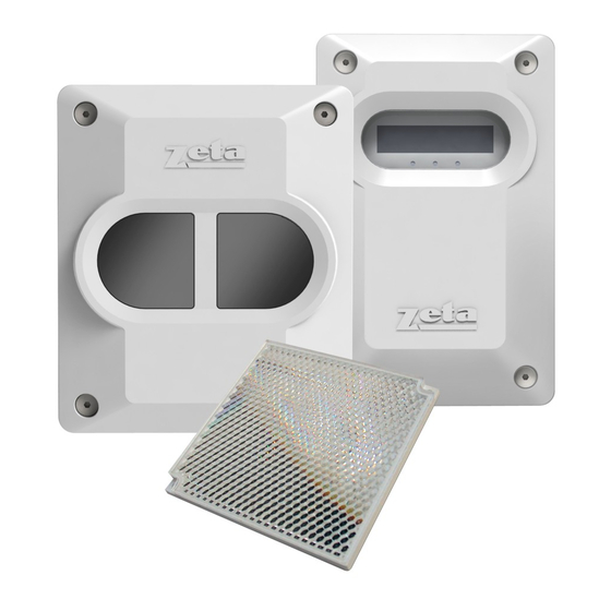
- Page 1 The ZetaBeam Protection System Xtra User Guide 0150-01...
- Page 2 The ZetaBeam Distance and position guidelines These guidelines are recommendations only and it is important that you refer to your appropriate governing standards at all times. When positioning your ZetaBeam there are important factors that you should consider, mainly what distance you are covering and the optimal position in the building.
- Page 3 What position? A roof is considered flat unless the height of the apex is greater then 0.6m. If the roof is flat the ZetaBeam system can be placed anywhere under the roof between 0.3m and 0.6m below the roof, up to a maximum height of from the floor.
-
Page 4: Step 1 Mounting The Head
2 Installing, commissioning and testing step 1 mounting the head Screw the head backing plate to the wall - always try to use as sturdy a location as possible, such as brick or major structural steels (avoid mounting to outer metal cladding etc). Avoid mounting the head where direct sunlight can shine directly into the ‘eyes’... - Page 5 Generic wiring configurations the ZetaBeam is a conventional device, below are suggested wiring configurations for single and multi heads on a zone. the ZetaBeam can easily be made addressable with the use of a manufacturers interface and in some cases can also be powered from the loop, ie with the Zeta ZAI-MI or SMM/B monitor.
- Page 6 Multiple beams on a zone Other wiring diagrams See our website for further diagrams including interfacing with manufacturers protocols www.zetaalarmsystems.com...
- Page 7 COVER it if already in place. You cannot commission the beam if the reflector can be seen Air Quality 0% ZETA Beam Status Fault 2. Power up the unit and you will see the screen will default to Xtra Air Quality 0%...
- Page 8 Receiver sensitivity (RX Sense) will start by rising to 100% and then the output power (IRpower) will rise to 100%. More power will be output than is necessary to cover the distance and these levels will then be reduced once the auto align process takes place. Pre-Align Complete will now be indicated Press enter to accept Pre-Alignment and confirm these settings by pressing the...
- Page 9 stage three, manual alignment Once Pre Alignment is complete you will enter Manual Alignment. NOW place or uncover the reflector When you install or uncover the reflector the Right hand Figure (AQ) will jump up as high as 135%, this clearly shows that the ZetaBeam can see the reflector and you can press Enter to move to Auto Alignment.
- Page 10 Stage four, auto-alignment Having received an AQ reading of over 100% in manual mode press enter to exit manual and enter again to go into auto alignment mode. 8.7% 67% 103% A Auto Alignment enter X+0.00° Y+0.00° Auto Alignment is an automatic process that will firstly reduce the RX Sense and IR Power to accommodate the best settings for the ZetaBeams environment.
-
Page 11: Home Screen
3 Screen and menu systems Home screen Air Quality 100% This is the screen you would normally see when the beam is commissioned. Status - NORMAL Other screens you may see are: Air Quality 29% FIRE The air quality level has fallen below the fire threshold setting. Status - FIRE If alarm is set to latching and you need to reset from fire press enter... - Page 12 Individual menu items enter 1. The language is factory set to English if this is okay press enter to continue to commissioning or arrow to return to the home screen. To change Language the language use the right left keys to change to your preferred language and press enter to confirm your choice –...
- Page 13 3. Here we can make changes to how the beam behaves. Press enter to go into enter Mode Change mode change and the sub menus. enter Threshold. Use the right left keys to increase or decrease the beams sensitivity. It is factory set at 35% (meaning the received signal has to drop by 35% to trigger Threshold the fire relay.
- Page 14 Green flashing light on / off. By using the right left keys you can turn the green Green Flashing flashing LED, located on the head and controller, or off. This is a useful way of Light On/Off identifying the beam head you are working with (press enter to return to mode...
- Page 15 Event counts. Here we can see how many times the beam has gone into fire fault Alarm & Fault since the beam was commissioned or since the event log was last cleared. Event Counts Press enter clear events. enter left/ Press left/back to return to...
-
Page 16: Technical Specifications
technical specifications Electrical Specifications: Test/Reset Features: Supply Voltage. 12 to 30 VDC Beam test function by controller Supply Current. 3.5mA (constant current) Alarm latching/auto-reset selectable in all operational states (default auto-reset) Constant Current. 17mA (constant current) Alarm reset in latching mode by controller reset in fast commissioning function, removing power for >5 seconds, apply >5 VDC to reset connections in Beam Head.
Need help?
Do you have a question about the Zeta Beam and is the answer not in the manual?
Questions and answers