Table of Contents
Advertisement
Quick Links
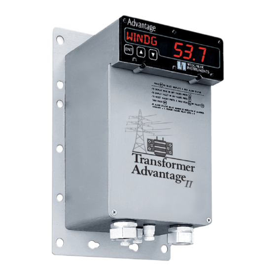
Transformer Advantage II Enhanced Series
Owners Manual
Manual Part Number OMAMT200
Revision 6, November 10, 2011
Use with Firmware AMTSYS0202, Revision 02 and Higher
(See Page 3 "Displaying Firmware Part Number")
16900 FOLTZ PARKWAY, CLEVELAND, OHIO 44149
440/238-2550, FAX 440/238-0660 e-mail:
sales@weschler.com
Advertisement
Table of Contents

Related Manuals for weschler instruments Advantage II Enhanced Series

Summary of Contents for weschler instruments Advantage II Enhanced Series
- Page 1 Transformer Advantage II Enhanced Series Owners Manual Manual Part Number OMAMT200 Revision 6, November 10, 2011 Use with Firmware AMTSYS0202, Revision 02 and Higher (See Page 3 “Displaying Firmware Part Number”) 16900 FOLTZ PARKWAY, CLEVELAND, OHIO 44149 440/238-2550, FAX 440/238-0660 e-mail:...
-
Page 2: Table Of Contents
Table of Contents Section Title Section Page Introduction ................1.0 ......1 Description, Models and Features, Intended Usage, Displaying Firmware Part Number, Feature and Module Locations Receipt Inspection . - Page 3 1.0 Introduction Description Advantage transformer monitors are compact, fully electronic, programmable instruments designed for accurate and reliable thermal management of liquid immersed power and distribution transformers. This manual describes the Enhanced SC, DC, TC, LTC, CT, CTX and CT/LTC models, collectively referred to as the Advantage IIE series. The standard Advantage IIE platform offers expanded alarm techniques, easier set-up, many user-convenience additions and provides the basis for expansion into advanced data collection and communications.
- Page 4 All of the Advantage IIE series models are capable of being equipped with option modules to allow them to perform functions that compliment their primary mission. The present option module offerings are the Multi-Channel Analog Retransmit (MCAR) module and the Load and Cooling Apparatus Monitoring (LCAM) modules. The MCAR module provides for up to 3 analog current loop outputs which are proportional to values measured or calculated by the Advantage.
- Page 5 Features Provided by the Optional LCAM Module i In SC, DC, TC and LTC models, monitoring of up to 8 analog or digital values with ranges from 5v to 300v AC or DC, and two low current ranges 0-1 and 0-20 madc. High AC current inputs are handled through air-core (Rogowski coil) CT’s.
-
Page 6: Feature And Module Locations (Surface Mounting)
Feature and Module Locations The feature locations are illustrated in Figure 1 below and Figure 2 on page 5. Detail dimensions are contained in the specifications section and Figure 21 and 24. Note that access to the modules is from the front for surface mount and from the rear for through-panel mount. For each of the two mounting configurations the modules are positioned in the same order, and slot position. -
Page 7: Feature And Module Locations (Through-Panel Mounting)
Figure 2. Rear View of Through-Panel Mount with Cover Removed Upper Cavity (behind backplane) Backplane Spacer Strips Power Supply Terminals Optional Communications Port 1 Input / Output Module Terminals Relay Module A Terminals. Module Shown Uses Clamp-On Optional Relay Module B (external) CT Option. - Page 8 3.0 Installation Internal Inspection Prior to operation, remove the cover plate and inspect the module cavity for accessories and shipping blocking items. In some cases spare parts bags may be placed in the bottom cavity for installation convenience. These bags contain terminal screws, jumpers and other items which may be misplaced during the installation process.
- Page 9 Terminal - by - Terminal Connection Guide All signal, power and control connections are made at the terminal strips mounted at the edges of the installed modules. If your Advantage is not equipped with a particular feature, the terminal screws will be omitted and replaced with plastic hole plugs.
-
Page 10: Power Supply Fuse Ratings And Sizes (Tables 1A & 1B)
Table 1A. Wide Range Power Supply Fuse Ratings and Sizes Power Supply Part Voltage Nominal Fuse Fuse Rating Fuse Type Figure Number (Range) Component ID 48 vdc (36-75 vdc) ¾ amp slow-blow 2AG (4.5 x 15 mm) 2000006301 90-264vac/85-300vdc ½ amp slow-blow “... -
Page 11: Power Supply And I/O Module Fuse And Jumper Locations (Figures 3A - 3E)
Table 3. Summary of Field Configurable Jumpers on Optional Advantage Modules (Figure 8). Model Module Jumper ID Function Position(s) LCAM Channel 1 Current / Contact Wetting 1ma, 20ma, Wetting, Off Channel 2 Current / Contact Wetting 1ma, 20ma, Wetting, Off Channel 3 Current / Contact Wetting 1ma, 20ma, Wetting, Off Channel 4 Current / Contact Wetting... - Page 12 Figure 3B. Wide Range Power Supply 2000006301 & Derivative 2000006303 Top View Thermal Shoe. DO NOT PRESS HERE Low Voltage Section Fuse F2 High Voltage Section Fuse F1 Figure 3C. 48 VDC Wide Range Power Supply Derivative 2000006302 Thermal Shoe. DO NOT PRESS HERE...
- Page 13 Figure 3D. 32 VDC Wide Range Power Supply Derivative 2000006304 Figure 3E. Typical Wide Range Power Supply & Derivatives Front Panel. Label for 2000006301 Shown Bus Voltage Bus Voltage Pull Here Indicator Lamps Test Switch to Extract Supply The terminal assignments on the wide range power supply differ from its predecessor to accommodate the two voltage ranges that it can be connected to.
- Page 14 thermal shoe, which transfers heat energy from the components to the case, where it can be dissipated to the outside environment. The shoe must be in intimate contact with the inside of the case, and it is therefore very important that the shoe not be distorted is any way, if the supply is removed.
- Page 15 RTD Inputs Either 3 wire or 4 wire RTD’s can be connected to the RTD inputs. The Weschler standard probe is 4 wire, chosen for enhanced probe accuracy regardless of lead length. The lead wire of the standard probe is 24 AWG and a crimp terminal suitable for 22-26 AWG wire and a #6 stud should be used.
- Page 16 19 to comply with the RS-485 specification. It is suggested that the system be tested first without the resistors, and if it performs properly, do not install it. TC and CT/LTC Models Hard wired connections for digital communications are made to the I/O module at terminals I/O-17 to I/O-21. RS-232 is connected to I/O-17 (comm transmit 1), I/O-19 (comm receive 1) and I/O-21 (digital comm ground).
-
Page 17: Wire Jumper Locations On The I/O Modules For Ct & Ctx (Fig 4A) And Ltc & Ct/Ltc (Fig 4B)
Figure 4A. 3-Wire RTD Jumper Location on the I/O Module for SC, DC, CT, CTX and LTC Models J3 RTD2 Jumper J2 RTD1 Jumper Figure 4B. 3-Wire RTD Jumper Locations on the I/O Module for TC and CT/LTC Models J4 RTD3 Jumper J3 RTD2 Jumper J2 RTD1 Jumper OMAMT200 Rev 6 Page 15 of 107... - Page 18 Relay Module Connections: Connections to the relay terminals can be made using the lugs described in the connections general section above. Lugs and hook-up wire conductor should be appropriate for the current level plus expected overloads. Hook up wire insulation should be chosen appropriate to the peak circuit voltage level.
-
Page 19: Six Form C Relay Module (Scrm) Jumper Locations
Figure 5. Six form C Relay Module (SCRM) Jumper Locations Jumper J2 Shown in Primary (CCA) Position Jumper J8 Shown in Normal (PB6) Position Jumper J5 Shown in Non-SPI Position CT Current Input Terminals Terminal CCA-20 Terminal CCA-19 Current Input Connections (CT, CTX and CT/LTC Models Only) If your model has a Polyphase Current Input (PCI) module or Load and Cooling Apparatus Monitoring (LCAM) module installed, the WTI winding current connections must be made to it. -
Page 20: Relay Operation For Various Alarm And Power Conditions
Connections to the current terminals can be made using the lugs described in the connections general section above. Lugs and hook-up wire conductor should be appropriate for the current level expected plus overloads. Hook up wire insulation should be chosen assuming an open circuit in the CT secondary could occur at any point in the circuit. Special attention must be taken when wiring to the current sense inputs if wiring directly to the WTI current transformer (CT), since the open secondary of a CT can generate high voltages which may be lethal to personnel. -
Page 21: Multi Channel Analog Retransmit (Mcar) Module
Optional Module Connections The modules in this section are not part of the Advantage standard hardware feature set. They are generally ordered as an optional feature at the same time as the Advantage, but may be ordered separately. In the latter case, installation instructions will be included with the module in the shipping carton. -
Page 22: Polyphase Current Input (Pci) Module
Polyphase Current Input (PCI) Module The Polyphase Current Input (PCI) module incorporates three separate, electrically isolated channels to convert the current signals from 3 individual CT’s into a single one to be displayed as ILOAD. The PCI incorporates circuitry to automatically compare the three signals and select the one having the greatest magnitude for display. - Page 23 Load and Cooling Auxiliary Monitoring (LCAM) Module The LCAM module is an eight channel multi-range input module that accepts AC and DC voltage and current in 9 ranges, plus 10 vdc contact wetting excitation on each input. The LCAM module must be used with Advantage II Enhanced Firmware in the AMTSYS family.
-
Page 24: Load & Cooling Apparatus Monitoring (Lcam) Module And Ranging Daughterboards (Figs 9A-9C)
Figure 9A. LCAM Module The module configuration shown has five analog multi-range circuits on the right side of the photo and 3 Clamp-on CT inputs to the left side of the photo. Retaining Plate Retaining Screw Volt Bypass Figure 9B. Figure 9C. -
Page 25: Summary Of Lcam Daughterboard Plug-In Settings
When the wetting range is selected, approximately 10 vdc is applied to the external terminals for wetting of unpowered contacts. Switches or relay contacts that are connected to a power source must not be connected to the terminals of any channel which has its hardware set up for contact wetting, otherwise the LCAM module may be permanently damaged. -
Page 26: Channel Assignments
Table 6. Channel Assignments Model Channel Number / Name Channel Inputs on Module Type of Input RTD1 RTD1 2 Ð RTD2 RTD1 2 Ð RTD2 3 Ð RTD3 RTD1 2 Ï RTD2 RTD1 I/O Õ AC Current RTD1 RTD2 I/O Õ AC Current RTD1 2 Ï... -
Page 27: Power And I/O Circuit Emi Protection (Figs 10A - 10E)
High Potential (Hi Pot) and Insulation Resistance (Megger) Testing Power and Input / Output Transient Protection Circuitry: The Advantage incorporates surge and transient suppression circuitry on its power, input and output circuits to protect sensitive internal electronic components from electrical disturbances which are common to the application environment. The suppression circuitry forms a classic filter and clamp network. - Page 28 MOV N1 N.O. MOV N2 N.C. MOV N3 Relay N MOV N4 Figure 10C. Alarm Relay EMI Suppression Networks Maximum voltage contact-to-contact is 250 Vrms. Maximum test voltage contact-to-earth is 2500 Vrms. OUT+ MOV1 TVS1 Retransmit Current OUT- MOV2 MOV3 EARTH Figure 10D.
-
Page 29: Terminal Assignments And Locations (Figs 11A - 11B)
Figure 11A. Terminal Assignments. SC, DC, LTC, CT & CTX Models with 6C/6C Relay Module Scheme The SC model’s analog retransmit output is always located on the I/O module. Terminal Screws on all modules except the I/O module have #6-32 threads. Do not mix I/O module screws with screws from another module, or thread damage will result. - Page 30 Figure 11B. Terminal Assignments; TC & CT/LTC Models with 6C/6C Relay Module Scheme Only the CT/LTC model has a WTI CT input. Terminal Screws on all modules except the I/O module have #6-32 threads. Do not mix I/O module screws with screws from another module, or thread damage will result. The actual model may not contain all optional hardware shown.
- Page 31 4.0 Configuration Introduction The configuration section describes actions the user can take to set up the Advantage for first use, or modify settings as required at other times. This section first presents the steps necessary to enter and navigate through the menus accessible from the front panel, through the use of graphical keystroke diagrams.
- Page 32 CT, CTX and CT/LTC Models Only (continued) Relay Set Up Summary: It is assumed that CT-series Advantage will operate cooling equipment as part of its winding temperature function, and in order to control the equipment the Advantage must be “told” what type of cooling equipment it is connected to, in the relay set up.
- Page 33 Examples for CT-Series Models with an LCAM Module If the LCAM module is installed there is an additional set of required parameters for each of the three current measurement channels that is enabled. Thus the list for a transformer with ONAN/ONAF/OFAF ratings with two current measurement channels enabled would be: Parameter Prompt...
-
Page 34: Configuration Loop Entry Keystroke Diagram
Display Keystroke Action Press and hold the ENTER button for 3 or more seconds. It FLUID 000.0 does not matter what title appears in the prompt display when entering the supervisor loop. CONFG OPER Press the UP button once to change the option display to "SUPER". CONFG Press the ENTER button once to select SUPERvisor option. -
Page 35: Main Configuration Loop Summary Keystroke Diagram
DISPLAY DISPLAY RELAY Set up triggers that will modify SEASN Set connected equipment, normal coil state,sense-fail SETUP SETBK set point values in response to coil state. Enable operator to check relay. a calendar date. Set alarm sources, setpoints, hysteresis, timed/calendar ALARM Enable/Disable operator mode alarm trigger sources, relay to be operated, relay pick-up... -
Page 36: Main Configuration Loop Detail Keystroke Diagram (Figures 14A - 14G)
Go To Operator 99999 Correct PASWD Keystroke Loop -9999 Password? Display Presentation VALUE PROMPT SETUP RELAY Configuration of relays 1- 12 is set up here. All relays are set up using the same keystrokes Symbol Definitions CHANG, ALARM Cooling SETUP Symmetrical ENTER DOWN... - Page 37 RELAY SETUP ALARM SETUP Set User Parameters for Thermal Profile Tailoring SILIC Display Presentation Specify fluid type USER SETUP TYPE FTYPE FLUID MINER ORGAN VALUE PROMPT Specify fluid capacity 50000 CPCTY FLUID GALLN in US Gallons Symbol Definitions RECTR TYPE Select winding construction WINDG WTYPE...
- Page 38 USER RELAY SETUP SETUP 99999 20.0 PRMRY SECND If the primary and secondary RATIO ratio factors are known, they SETUP CT 1 CT 1 CALCT can be entered directly at the SIGNL HIGH PRMRY and SECND prompts. ZERO1 0.00 CT 1 PRESENT ZERO Valid Cal...
- Page 39 RELAY SETUP SETUP Values for EOL (End Of Life) hours and IEL (Initial Expended Life) hours ranges from 0 to 300000 LIFE INSUL EOL 1 50000 IEL 1 50000 but the factory default is 150000. LTC & CT/LTC MODELS ONLY. Disables all LTC differential functions Including display, set point alarms and peak and valley recording. FUNCT On LTC models, setting this to OFF effectively changes the Advantage into a top oil temperature indicator.
- Page 40 DSPLY RELAY ENABL SETUP The TIMED TRGGR function allows for turning alarm relays on and off in response to clock or calendar set points, which are triggered by the real-time clock. Time units are HH.MM where HH is Hours and MM is Minutes. DAILY WEEK TIMED...
- Page 41 SCALE RELAY RANGE SETUP 99999 CALIB SYSTM PASWD -9999 NEXT 250.0 LAST POINT -90.0 POINT? EXIT TABL1 TBLEN EXIT POINT TLEN1 TLEN1 EXIT CORRECT PASSWORD? CHANNEL 2 ON ? NEXT 250.0 LAST POINT -90.0 POINT? EXIT TABL2 TBLEN EXIT POINT TLEN2 TLEN2 EXIT...
- Page 42 FROM RELAY SYSTM SETUP CALIB Run the self-check operation. When CALYS is selected, the internal reference resistors are measured CALYS WAIT and their equivalent thermoresistive (temperature) value is stored as an INREF temperature. This SELF CHECK SLFCK temperature is normally 0.0 +/- 5 degrees C and can be displayed from the Operator Menu. See the CALNO prompt INREF on the Operator Mode keystroke diagram for more details.
- Page 43 4.0 Configuration (continued) Keystroke by Keystroke Guide to Setup This guide describes operation of the functions and options available in the various front panel menus. It is structured and sequenced in the same order as the keystroke diagrams for a direct reference as values are entered. The paragraphs which describe the prompts in the main menu loop level are placed on the left margin.
- Page 44 Cooling Equipment Characteristics Mode Code ONAF Fans, no Pumps Air circulated through heat exchangers by fans OFAN Pumps, no Fans Fluid circulated in the tank and heat exchangers by pumps OFAF Fans and Pumps Air circulated through heat exchangers by fans and fluid circulated in the tank and heat exchangers by pumps.
- Page 45 The informative variable CHANG is the default value which only remains displayed if the connected equipment has never been declared. This is a signal to the Advantage that the value needs to be changed. If you do not change this value to another informative value or an effective value you will be returned to the connected equipment menu item to correct the error.
- Page 46 Prompt COIL, Relay Coil Un-Alarmed State Variable The COIL function offers a choice of two coil states; DE-EN, (de-energized) which shuts off power to the relay coil in an un-alarmed condition; and ENRGZ (energize) which applies power to the relay coil in an un-alarmed condition. These two choices are provided in order to be able to set up fail safe relays.
- Page 47 sensor and internal functions for correct operation. If a gross malfunction of the sensor, such as an open or shorted condition occurs, the event causes an alert signal to be sent to the alarm logic indicating that a failure has been detected. This alert signal will cause any alarm with a winding or fluid temperature alarm source and its SNFAL option set to ENABL to operate its assigned relay.
- Page 48 Model Measurement Channel Source RTD (note 1) TOPO, TOPO1, TOPO2, TOPO3 or FLUID Winding Current (note 2) LCAM1-LCAM3 CRNT1, CRNT2, CRNT3, HCRNT (With Winding Temp (note 2) WIND1, WIND2, WIND3, HIWND LCAM) Insulation Life (note 5) LOL1, LOL2, LOL3 AUX (note 2,3) LCAM2-LCAM8 LCAM2, LCAM3, LCAM4, LCAM5, LCAM6, LCAM7, LCAM8 TOPO, TOPO1, TOPO2, TOPO3 or FLUID RTD (note 1)
- Page 49 Model Measurement Channel Source Winding Current (note 3) LCAM1-LCAM3 CRNT1, CRNT2, CRNT3, HCRNT Winding Temp (note 3) WIND1, WIND2, WIND3, HIWND Insulation Life (note 5) LOL1, LOL2, LOL3 AUX (note 2, 3) LCAM2-LCAM8 LCAM2, LCAM3, LCAM4, LCAM5, LCAM6, LCAM7, LCAM8 Sensor Failure SNFAL None...
- Page 50 supervised by connecting the SFR’s contacts in series with the set point alarm relay. The SFR contacts are timed to open before the set point relay’s contacts close, and close after the set point relay’s contacts open. This arrangement effectively blocks the nuisance alarm, but requires an additional relay. The SNFAL (sensor failure) alarm source is provided in all alarm set up menus, thus allowing any alarm to be set up as a sensor failure alarm.
- Page 51 logic section. However slight the increase in program execution load is, the branch into the switching logic section creates a senseless increase in execution complexity and reduces reliability. Prompt SEASN SETBK, Seasonal Setback, Figure 14A All Models This variable provides for enabling the seasonal setback function on an individual alarm basis. The parameters that govern the function must be set up in the SEASN SETBK loop, on the main menu level, in order for this function to have an effect on the alarm.
- Page 52 Prompt DRPOT, Relay Drop-Out Delay, Figure 14A All Models The DRPOT (drop out) function is provided to delay the drop out of a relay from an alarm state. This is used primarily in alarm schemes to avoid nuisance trips. In these schemes supervisory relays are delayed for a certain period to give alarm relays time to reset before the supervisory period is over.
- Page 53 The DRY selection is provided to indicate to the operating system that an un-powered switch or relay contact is to be connected to the LCAM input. The full scale value is set to approximately 10 volts by hardware and the high and low thresholds are automatically set to 5v for ON / OFF signaling.
- Page 54 For voltage monitoring, the motor voltage level is set in LCAM hardware and as the full scale value in the SCALE dialog above. The input leads are then connected across the cooling apparatus motor leads. This is mostly an on / off monitoring, but extreme voltage drops due to shorted motor windings or blown fuses can be detected.
-
Page 55: Lcam Alarm Hysteresis Diagram
FULL ALARM REGION VALID BAND LIMITS LOW ALARM HIGH ALARM VALID BAND LANDING ALARM ZONE HYSTERESIS HIGH ALARM HYSTERESIS ZERO FULL SCALE SCALE OVER RANGE REGION Figure 15. LCAM Alarm Hysteresis Diagram Referring to figure 15, the unalarmed zone in valid band alarms is between low alarm and high alarm set points. Thus, the hysteresis value acts above the lower set point and below the upper set point. - Page 56 Prompt OPRAT, Driven Relay Definition, Figure 14A LCAM Equipped Models Only This function operates exactly the same as the standard alarm function of the same name. Prompt USER SETUP, User Loop, Figure 14B (CT, CTX and CT/LTC Models Only) In the USER SETUP menu there are a maximum of 17 values (43 values with LCAM) for the winding temperature function which may be entered.
- Page 57 The Advantage winding temperature algorithm WTA uses equations which are based on the logic and mathematical relationships which are expressed in the IEEE Guide for Loading Mineral-Oil-Immersed Transformers, IEEE Std C57.91- 1995. The Guide considers many more variables than the Advantage WTA for two reasons. Firstly, many of the guide’s equations are used to calculate the theoretical top oil temperature.
- Page 58 Prompt WINDG CURNT Maximum Winding Current Sub-Menu, figure 14B (Required Parameter) (CT, CTX and CT/LTC Models Only) The WINDG CURNT prompt provides a sub-menu to set the value(s) of maximum winding current passing through the winding being measured. The sub-menu requires a value for each winding being measured. If an LCAM module is not installed, only a single value will be required.
- Page 59 The prompt for the ONAN gradient is GRAD1, GRAD2 or GRAD3. Since you are in the ONAN SETUP menu, the ONAN prefix is understood. The ONAN gradient is the temperature differential between the temperature of the fluid at the top of the tank (top oil temperature) and winding temperature(s), when fluid and air are circulating through heat exchangers without the aid of pumps or fans.
- Page 60 The EXP (exponent) values may vary widely depending upon transformer design, and it is therefore advisable to analyze the resulting values carefully. In most cases the ONAN gradient will be calculated to be on the conservative side. If you have no idea as to what the EXP value might be, the recommended values are: Cooling Mode at Maximum Rating Exponent Value ONAF...
- Page 61 Where: MAXGRAD The gradient value provided for the 1 Per Unit (100%) load rating of the transformer. This rating will correspond to the all-cooling-on mode, for the winding being measured. ONAF MVAX The load rating corresponding to the ONAF cooling mode. The “X” corresponds to the winding being measured.
- Page 62 Prompt OFAF SETUP, OFAF cooling mode power and gradient entry menu. Figure 14B (Required Parameter) (CT, CTX and CT/LTC Models Only) The OFAF SETUP menu provides for entry of power ratings and gradient values for the winding(s) being measured for winding temperature. If an LCAM module is not installed there will only be prompts for the power rating (prompt MVA1) and gradient (prompt GRAD1) for the first winding.
- Page 63 much more noise than pumps. The ODAN mode differs from the simple oil forced cooling schemes (OFAN, OFAF) in that the fluid that is pumped out of the heat exchangers is directed into the bottom winding ducts using a manifold arrangement.
- Page 64 Prompt CT1 SETUP, CT2 SETUP, CT3 SETUP, Current Transformer Ratio Setting Loop, figure 14C (CT, CTX and CT/LTC Models Only) The CTx SETUP loops are provided to match the current sense circuit’s ranges to the transformer’s Winding Temperature Indicator CT (WTI CT), which supplies the load current sense signal for use by the winding temperature algorithm.
- Page 65 depending upon the EOL criteria adopted by users. This value assumes dry insulation with low oxygen content and a constant insulation temperature of 110 EC for that entire period to EOL. Obviously a constant 110 EC winding temperature is impossible to guarantee in the real world, so the method was refined to allow for instantaneous measurement that was accumulated over the life of the transformer.
-
Page 66: Channel Titles
The Advantage includes an adaptive algorithm which “learns” the correct delay period for the corresponding user-specified step size, in response to application conditions. This feature will vary the initial user-entered LTC DELAY period by as much as ± 50% in response to measured signals. Basically, if the end of the delay period is reached and the actual differential value exceeds the step size, the Advantage will shorten the delay period to try and capture a smaller segment of the signal. - Page 67 TOPO, TOPO1, TOPO2, TOPO3, FLUID LTCTK CT/LTC (LTC Function ON) TOPO, TOPO1, TOPO2, TOPO3, WINDG, XWIND, YWIND, HWIND, 3 (note 2,3) BOTTO, AMBNT, MANTK, FLUID or OFF TOPO, TOPO1, TOPO2, TOPO3, FLUID TOPO, TOPO1, TOPO2, TOPO3, WINDG, XWIND, YWIND, HWIND, 2 (note 2) CT/LTC BOTTO, AMBNT, LTCTK, MANTK, FLUID or OFF...
- Page 68 If an input is being enabled for the first time, or is being re-enabled after being disabled, the channel’s display will need to be turned on in the DSPLY ENABL loop in order for it to be seen on the front panel display. Prompt DSPLY ENABL, Channel Display Option Loop, Figure 14D All Models The DSPLY ENABL loop is provided to allow users to turn off the display of values on the front panel.
- Page 69 The SEASN SETBK function also allows for seasonal adjustment of alarm(s) which operate in response to load current (ILOAD) magnitude. The AMP variable of this feature provides for a ± 500 amp range of adjustment, referred to the maximum load current, which is the “IMAX” value declared in the USER SETUP loop. Refer to 16C for the menu location of this variable.
-
Page 70: Retransmit Sources
Table 9. Analog Retransmit Sources Model Measurement Channel Source (note 1, 2) TOPO, TOPO1, TOPO2, TOPO3, WINDG, XWIND, YWIND, HWIND, WIND1, WIND2, WIND3, BOTTO, AMBNT, LTCTK, MANTK or FLUID TOPO, TOPO1, TOPO2, TOPO3, WINDG, XWIND, YWIND, HWIND, WIND1, WIND2, WIND3, BOTTO, AMBNT, LTCTK, MANTK or FLUID TOPO, TOPO1, TOPO2, TOPO3, WINDG, XWIND, YWIND, HWIND, WIND1, WIND2, WIND3, BOTTO, AMBNT, LTCTK, MANTK or FLUID MANTK... - Page 71 Model Measurement Channel Source (note 1, 2) TOPO, TOPO1, TOPO2, TOPO3 or FLUID LTCTK TOPO, TOPO1, TOPO2, TOPO3, WINDG, XWIND, YWIND, HWIND, CT/LTC BOTTO, AMBNT, LTCTK, MANTK or FLUID (LTC Function ON & With LCAM) LTC Differential DIFF, DEV Winding Current LCAM1-LCAM3 CRNT1, CRNT2, CRNT3, HCRNT Winding Temp WIND1, WIND2, WIND3, HIWND...
- Page 72 SETUP loop. When a CT-series Advantage is equipped with an LCAM module which is monitoring winding current, there may be up to three current values that can be retransmitted. As an example, if the user wants to produce a 4 to 20 ma output, based on the current range between 0 and 1000 amps, (s)he would set this value to 1000.
- Page 73 calibration coefficient can be entered only through the AMTCMF0201 software. Consult the SMAMT200 software manual for details regarding transferring the coefficient. Units which are being upgraded from firmware from MATSYS0201 and later will have their coefficients transferred automatically. Prompt SCALE RANGE, Select High Endscale Value, figure 14E The SCALE RANGE variable is set according to the expected highest measured temperature.
- Page 74 schedules for DST differ from the US. If the start and end dates at your location do not agree with the above schedule, the decision will need to be made whether to enable or disable the feature on an individual basis. If an overlap of a few days or weeks is less of a hardship than visiting the site to change the time twice a year, it may be more fitting to enable the feature.
- Page 75 Prompt BAUD, Set Communications Baud Rate, Figure 14G Seven baud rates are provided; 2400, 4800, 9600, 19200, 38400, 57600 and 115200 bits per second. The typical PC port is auto-negotiating, meaning it will find the correct baud rate for the connected device. This is not always true of applications, however.
- Page 76 Prompt COMM SETUP, Set Communications ID’s, Enable and Set Up Communications Protocols, Figure 14G Prompt ID, Communications Unit Identifier, figure 14G The communications unit identifier is a two digit number with a range of 00 to 99. It is used when communicating with two or more communicative devices which share the same communications bus (cable).
- Page 77 ModBus Prompt MODE, Communications Protocol Type, figure 14G The ModBus communications protocol type variable has two options, RTU or ASCII. ModBus Prompt PORTS, Display / Choose Port, figure 14G The PORTS prompt is actually a read only display which shows which ports will communicate using the selected protocol, which is this case is ModBus.
- Page 78 5.0 Operation Walk-up Functions The walk-up functions are those which can be performed while in the normal operating mode, with single keystrokes or dual simultaneous keystrokes. The functions affect the display and storage of measurement information. Any of the titles in the walk-up display loop may be stepped through and the PEAK and VALLEY values and corresponding time stamp may be viewed and reset.
-
Page 79: Walk-Up Menu Keystroke Diagram
WALK-UP DISPLAY SEQUENCE. SHOWN WITH ALL DISPLAYS ON. TITLES MAY VARY, DEPENDING UPON USER PREFERENCES 00000 00000 00000 00000 00000 00000 TITL1 WIND1 WIND2 WIND3 HIWND CRNT1 00000 00000 00000 00000 00000 00000 CRNT2 CRNT3 HCRNT TITL2 TITL3 DIFF 00000 00000 00000 00000... - Page 80 Relay Annunciator Displays The relay display is designed to inform the operator of which relays are currently active. It is a two-page display, meaning that if a relay higher than number 9 is active, a second relay display will appear when the ENTER button is pressed with the first relay display shown.
-
Page 81: Sensor And Internal Failure Alarm Displays
pressed a second time. In order to allow an operator to use the relay check function, the function must have been previously enabled. The relay check function is enabled in the main configuration loop, within the RELAY SETUP configuration sub- loop. -
Page 82: Operator Menu Keystroke Diagram (18A & 18B)
TO SUPERVISOR MODE SUPER OPERATOR FLUID 12345 CONFG Values are Viewed Only in Operator Mode. MODE OPER To Change Values, Go To Supervisor Mode. ENTRY Hold ENT for 3 seconds Select OPER Operator TO NORMAL MODE Mode Enabled ? Configuration of relays 1- 12 is viewed here. All RELAY SETUP relays are viewed using the same keystrokes. - Page 83 RELAY ALARM SETUP SETUP DGRE1 The INTNL REFNC function displays the temperature equivalent of the internal reference resistors for dignostic REFNC INTNL DGRE2 purposes. The values displayed range from -5.0 to +5.0 degrees. See the "Sensor and Internal Failure Alarm" DGRE3 paragraph in this section for details regarding the internal failure check function.
- Page 84 6.0 LTC Tailoring (LTC and CT/LTC Models Only) Why Measure LTC Differential Temperature? When the contacts of the LTC switch age or become worn, resistance to current passage increases. Since heat is created when a current is passed through a resistance (I R), the heat developed in the contact increases as the contact wears.
- Page 85 Probe Effects and Influences The LTC differential temperature varies very, very slowly in a transformer experiencing normal aging. There are several influences which can effect the accurate measurement of true differential temperature. They are listed below, by probe type: Thermowell Probe: 1.
- Page 86 clean tank walls. Interface enhancement is accomplished by probe design and the application of a stabile, thermally conductive compound between the clean tank wall and the sensor pad. The second line of defense is selection of the correct step and magnitude values. These values must be selected by the user, since each application is unique.
-
Page 87: Relationship Between Step And Delay Variables
Relationship of LTC STEP and LTC DELAY The step and delay variables of the differential software filter are analogous to the gain and time constant of an analog filter. The delay period auto-tune feature of the software filter is analogous to an automatically adjustable time constant of the analog filter. - Page 88 Determining the Differential Temperature Set Point The filtered differential temperature is the value which operates the DIFF set point alarm. The instantaneous differential temperature, as noted above, is the result of taking the difference between the main and LTC tank temperatures. The difference is taken after the RTD probe offsets are added to the measured temperatures.
- Page 89 7.0 Calibration The calibration of all Advantage models requires 2 distinct operations; self-check reference calibration and linearizing table entry. The self-check operation can be easily performed from the front panel, with just a few keystrokes. The linearizing table calibration operation can be performed from the front panel programming buttons or, with the communications feature, from a personal computer using Weschler configuration, monitor and flash (CMF) software.
- Page 90 Caution! Lethal voltages are generated when the secondary circuits of transformer CT’s are opened, while the transformer is energized. Take all precautions to ensure personnel safety before disturbing CT wiring. Best practice is to de-energize the transformer while working on CT circuits. 1.0 Setting the zero input point.
- Page 91 Verify the current circuit integrity. If you are calibrating to a bushing CT, remove the safety jumper from the terminals in the control cabinet which is connected to terminals CCA1 and CCA2 of the Advantage I/O module, or terminals PCI-8 and PCI-9 of the Advantage PCI module.
- Page 92 calibration technicians, by contacting the sales office at the phone number or website printed on the front cover of this document. The calibration operation simply allows the technician to “tell” Advantage what value to display at up to 12 defined points within the scale range.
- Page 93 12. If the unit under test is a TC or CT/LTC, and channel 3 is not turned off, the “TABL3” prompt will appear. Channel 3 is turned off by setting its title to “OFF” in the CHNL3 TITLE loop. See the CHNL3 TITLE function on Figure 14D. The operation for loading table 3 is identical to table 1, except the prompts referred to as TABL1 above will be TABL3.
-
Page 94: Temperature / Resistance Rtd Equivalence
Table 10 Temperature / Resistance RTD Equivalence Calibration Temperature Resistance Calibration Temperature Resistance Point ( EC ) ( Ω ) Point ( EC ) ( Ω ) Number Number -90.0 64.30 110.0 142.29 -40.0 84.27 140.0 153.58 -10.0 96.09 170.0 164.76 20.0 107.79... - Page 95 Calibration of Analog Retransmit Outputs (Single channel and MCAR) Configuration files created by the configuration software include analog retransmit settings for zero and full scale source and output range, and user coefficient. See the section covering analog retransmit setup, beginning with “Prompt ANRTN SETUP”...
-
Page 96: Amtcmf Software Analog Retransmit Calibration Screen
Figure 20. AMTCMFSoftware Analog Retransmit Calibration Screen Firmware Upgrade; Direct Coefficient Entry The direct method of coefficient entry is not a true calibration operation; it is the transfer of a coefficient that was determined during a previous calibration operation. In Advantage models with firmware versions prior to AMTSYS0201, the RFULX variable was adjusted to set the current output to within the ±0.5% stated accuracy limits. - Page 97 8.0 Troubleshooting Digital Communications Troubleshooting It has been found, from experience, that more than 90% of communications problems are due to cabling deficiencies and configuration errors. The remaining 10% of problems are typically divided into application problems (6%), hardware failures (2%) documentation errors (2%).
- Page 98 errors if the last bit transmitted is low, because the receivers must be idle in the logic high state, in order to determine when a communication has begun. If the logic state is low continuously, framing errors will result, causing communications to fail. If communications are poor or are not functioning and an RS-485 2-wire scheme is in use, bus bias could be the problem.
- Page 99 the I/O module without removing the wiring to the block. Loosen the small screws on either end of the block and unplug it. Remember to re-tighten the screws after reinstalling the block. If the problem is not resolved, shut off power, replace the original I/O module, substitute the Input Conditioning and Data Display module and run INTNL REFNC again.
-
Page 100: Specifications (Tables 11A & 11B)
9.0 Specifications Table 11A Advantage Detail Specifications Accuracy: Environment: Display Operating Temperature -40 to 70EC Temperatures (Measured) ± 0.1 EC -55 to 70EC (with Heater) Calculated Winding Temperature ± 1.0 EC Storage Temperature -40 to 85EC Nema 4X+ Current ± 1.0 % Fullscale Enclosure LTC (Thermowell / Mag Probe) ±... - Page 101 Table 11B. Load and Cooling Auxiliary Monitoring Module Specifications Channel Description: Temperature CT, CTX and CT/LTC Models Signal Type: Ranges (0 - full scale): Accuracy Coefficient (above 5% of full scale): Dedicated AC Amps 0-10 amps LCAM1, LCAM2, LCAM3 with internal CT ±...
- Page 102 Resistive Load DC voltages above 30 volts may require contact protection in addition to the MOV’s supplied. This protection is usually provided by clamp diodes connected in shunt to the load in a polarity which will block conduction to energizing current. The accuracy of the sensor in magnetically attached probes is the same as for the thermowell-mounted probes, however;...
-
Page 103: Surface Mount Outline And Drilling
Figure 21. Surface Mount Outline and Drilling OMAMT200 Rev 6 Page 101 of 107... -
Page 104: Recommended Surface Mounting Methods
Figure 22. Recommended Mounting Methods for Surface-Mount Cases E NT OMAMT200 Rev 6 Page 102 of 107... -
Page 105: Prohibited Surface Mounting Methods
Figure 23. Prohibited Mounting Methods for Surface-Mount Cases OMAMT200 Rev 6 Page 103 of 107... -
Page 106: Cut-Out And Drilling For Through-Panel Mount Cases
Figure 24. Cut-Out and Drilling Dimensions for Through-Panel Mount Cases Supplied with one permanent steel and one temporary plastic hole plug. Supplied with one RTD cable grip for each required RTD. Spare holes are capped with plastic screw plugs. OMAMT200 Rev 6 Page 104 of 107... -
Page 107: Communications Port 1 Cabling
All Weschler Instruments Transformer Advantage products are warranted against defects in material and workmanship for a period of five years from date of delivery. Weschler Instruments, at its option, will repair or replace any defective product returned to it during the warranty period without charge, provided there is no evidence that the equipment was mishandled or abused. -
Page 108: Index
INDEX Alarms DRY Contact ....See Module Connections, LCAM Conventions ......44 Features . - Page 109 Password Supervisory Mode Entry ....32, 34 Changing ......40, 75 Default .
- Page 110 Correction to Transformer Advantage II Enhanced Series Owners Manual Document: OMAMT200 The diagram for the Digital Communications Port 1 Adapter Cabling is incorrect. The correct information is shown below. This information replaces: Figure 21 in Revision 2, Figure 26 in Revision 4, Figure 27 in Revision 5, Figure 25 in Revision 6.
Need help?
Do you have a question about the Advantage II Enhanced Series and is the answer not in the manual?
Questions and answers