Table of Contents
Advertisement
Quick Links
INSTALLATION, OPERATION AND
VERTICAL TUBE HEATING COILS
MV & VIFB MODELS
ATTENTION: READ THIS MANUAL AND ALL LABELS ATTACHED TO THE UNIT CAREFULLY BEFORE
ATTEMPTING TO INSTALL, OPERATE OR SERVICE THESE UNITS! CHECK UNIT DATA PLATE FOR
STEAM OR HOT WATER REQUIREMENTS AND ELECTRICAL SPECIFICATIONS AND MAKE CERTAIN
THAT THESE AGREE WITH THOSE AT POINT OF INSTALLATION. RECORD THE UNIT MODEL AND SE-
RIAL No.(s) IN THE SPACE PROVIDED. RETAIN FOR FUTURE REFERENCE. THE APPLIANCE IS NOT
TO BE USED BY PERSONS (INCLUDING CHILDREN) WITH REDUCED PHYSICAL, SENSORY OR MEN-
TAL CAPABILITIES, OR LACK OF EXPERIENCE AND KNOWLEDGE, UNLESS THEY HAVE BEEN GIVEN
SUPERVISION OR INSTRUCTION. CHILDREN SHOULD BE SUPERVISED TO ENSURE THAT THEY DO
NOT PLAY WITH THE APPLIANCE.
WING Model No.
Wing MV & VIFB coil performance
is certified by the Air-Conditioning,
Heating, and Refrigeration Institute
(AHRI) under AHRI Standard 410
for maximum working pressures
up to 200 PSIG and temperatures
up to 400° F.
WARNING: Improper installation, adjustment, alteration, service or maintenance
can cause property damage, injury or death. Read the installation, operating and
maintenance instructions thoroughly before installing or servicing this equipment.
Installer Please Note: This equipment has been test fired and inspected. It has been shipped
free from defects from our factory. However, during shipment and installation, problems such as
loose wires, leaks or loose fasteners may occur. It is the installer's responsibility to inspect
and correct any problems that may be found.
ATTENTION: READ CAREFULLY BEFORE ATTEMPTING TO INSTALL, OPERATE OR SERVICE THIS
EQUIPMENT. RETAIN FOR FUTURE REFERENCE.
POST AND MAINTAIN THESE INSTRUCTIONS IN LEGIBLE CONDITION.
MAINTENANCE MANUAL
SAVE THIS MANUAL
INSTALLER'S RESPONSIBILITY
4830 TRANSPORT DRIVE, DALLAS TX 75247
TEL.: (214) 638-6010
www.ljwing.com
Serial No.
Wing MV & VIFB coils are listed
by Engineering Test Laboratories
(ETL) to Underwriter Laboratories
(UL) Standard 1995. This
standard assures that Wing coils
are safe to operate up to a design
pressure of 100 PSIG.
IOMVIFB-8
Advertisement
Table of Contents

Subscribe to Our Youtube Channel
Summary of Contents for LJ Wing MV
- Page 1 NOT PLAY WITH THE APPLIANCE. WING Model No. Serial No. SAVE THIS MANUAL Wing MV & VIFB coil performance Wing MV & VIFB coils are listed is certified by the Air-Conditioning, by Engineering Test Laboratories Heating, and Refrigeration Institute (ETL) to Underwriter Laboratories (AHRI) under AHRI Standard 410 (UL) Standard 1995.
-
Page 2: Table Of Contents
SECTION I - FOREWORD Table of Contents As is the case with any fine piece of equipment, care must be taken to provide the proper attention to the Section I: Foreword and Table of Contents ....2 operation and maintenance details of this machine. Section II: General Information ........2-3 Section III: Installation and Mounting Procedure ..3-4 This manual of instructions has been prepared to help... -
Page 3: Section Iii: Installation And Mounting Procedure
CAUTION - COIL MAY BE UNSTABLE ON FORKS to provide quick and dependable servicing of heating AND SHOULD BE SECURED FROM TIPPING BY coils. Wing also offers factory start-up service which ATTACHING CABLES OR CHAINS FROM TOP OF includes the presence of a service engineer to UNIT TO VERTICAL TRACKS OF FORK LIFT. - Page 4 STEAM/HOT WATER COILS headers by installing sheet metal isolation plates 1. Steam pipes must be sized to handle desired steam on the top and bottom upstream of the coils. flows at the lowest pressures. (b) Inlet and outlet mains should be fully insulated. (c) To eliminate coil temperature override, use slow –...
-
Page 5: Section Iv: Ductwork And Transitions
SECTION IV - DUCTWORK AND TRANSITIONS A. To obtain rated performance from the coils and B. Turning vanes must be used to assure even to eliminate air temperature control problems due distribution of air over the entire coil where elbows are to improper duct design and/or installation, use the used in the inlet and/or outlet side of a preheat coil. -
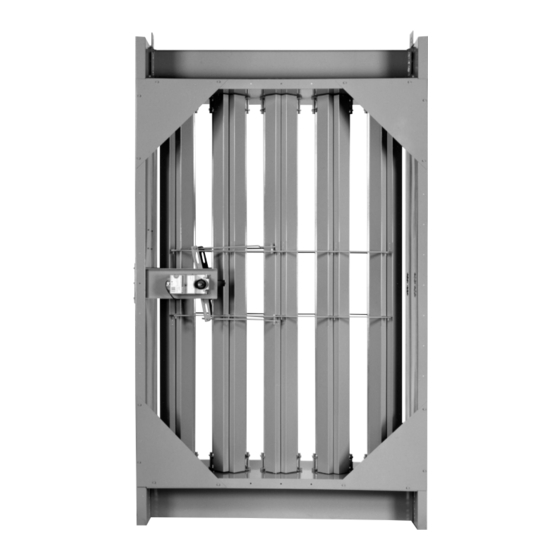
Page 6: Section V: Equipment Photos
SECTION V - EQUIPMENT PHOTOS Photo of Indirect-Coupled VIFB (Entering Air Side) Photo of Indirect-Coupled VIFB (Leaving Air Side) – 6 –... - Page 7 Photo of Direct-Coupled VIFB (Leaving Air Side) Photo of Direct-Coupled VIFB (Entering Air Side) – 7 –...
-
Page 8: Section Vi: Parts Drawing
SECTION VI - PARTS DRAWING Enlarged View C Section A-A Elevation Section D-D – 8 –... - Page 9 Section B-B Section B-B Section B-B 2 Row Hot Water 2 Row Steam 1 Row Steam or Hot Water No. Description No. Description Side Panel Drive Side Bearing Nylon Angle Lifting Eye Washer - Special Finned 5/8" Tube Supply Header Closed-Circuit Header Damper Plain Washer –...
-
Page 10: Section Vii: Piping
The integrity of the system depends in part on proper 12. Each coil in a coil bank or in series should be piping. The following recommendations should be individually trapped and vented. MV coils require diligently observed: two traps. Steam Systems 13. - Page 11 STEAM PIPING VIFB Coil Piping Diagram – 15 psig and below W12A – 11 –...
- Page 12 STEAM PIPING VIFB Coil Piping Diagram – Above 15 psig W33B – 12 –...
- Page 13 HOT WATER PIPING VIFB Coil Piping Diagram – One or Three Row Coils W13B – 13 –...
- Page 14 HOT WATER PIPING VIFB Coil Piping Diagram – Two Row Coil W32B – 14 –...
- Page 15 STEAM PIPING MV Coil Piping Diagram – 15 psig and below W27A – 15 –...
- Page 16 STEAM PIPING MV Coil Piping Diagram – Above 15 psig W28A – 16 –...
- Page 17 HOT WATER PIPING MV Coil Piping Diagram – Two Row Coil W29A – 17 –...
-
Page 18: Section Viii: Control Installation And Adjustment
SECTION VIII - CONTROL INSTALLATION AND ADJUSTMENT A. The Wing coil controls airstream temperature C. Control installation instructions, including by changing face and by-pass damper positions in diagrams, are enclosed in the instruction envelope response to the signal produced by an airstream when special controls and control arrangements thermostat in the downstream ductwork. - Page 19 ELECTRIC AND PNEUMATIC CONTROLS D000756A – 19 –...
- Page 20 D. Adjustment Procedure for Damper Linkage of Photo 1 Coils with Side-Mounted Actuators: 1. Disconnect damper motor rod at ball joints. 2. Loosen all ball joints on scissor saddle (base pan) assembly. 3. Place scissor saddle (base pan) in an “X” configuration.
-
Page 21: Section Ix: Start Up
SECTION IX - START UP A. Control Checks C. Turning Hot Water On Unit 1. On units with PNEUMATIC CONTROLS, take all (Be sure lower header(s) shipping bolts are removed) air pressure off. Dampers should go to full face 1. Open return valve and supply valve. Purge all air open position. -
Page 22: Section X: Shut Down
SECTION X - SHUT DOWN A. Shut off system air fan. D. As soon as possible, open drip leg in return main (on steam units), or drain and air valves (on hot water B. Close system outside air shutters or otherwise units), and allow water to drain. - Page 23 – 23 –...
- Page 24 4830 TRANSPORT DRIVE, DALLAS TX 75247 TEL.: (214) 638-6010 www.ljwing.com...
Need help?
Do you have a question about the MV and is the answer not in the manual?
Questions and answers