Table of Contents
Advertisement
Quick Links
Advertisement
Table of Contents

Summary of Contents for Weidmüller PV DC COMBINER BOX
- Page 1 PV DC COMBINER BOX Operating instructions...
-
Page 3: Table Of Contents
Contents About this documentation Connection of the communications (optional) Target group and contents Wiring the communications Symbols and notes Connecting the RS485 to the Transclinic 6.3 Configuration of the Modbus address and the RS485 serial Safety settings General safety notice Recommendations when using serial converters Intended use 6.5 Recommendations when configuring the SCADA Personnel Commissioning Legal notice... -
Page 4: About This Documentation
This user manual is intended to personnel that is involved in mechanical and electrical installation of a Weidmüller Symbol Meaning PV DC COMBINER BOX and moreover to service and Warning against hazardous electrical voltage maintenance personnel. This user manual gives the general overview about the complete range of PV DC COMBINER BOX, the individual components, their function as well as their correct handling. -
Page 5: Safety
2.2 Intended use The PV DC COMBINER BOX series are intended for use in photovoltaic (PV) systems. The product joins different strings of a PV system and contains DC over-current and over-voltage protections for string level. -
Page 6: Device Description
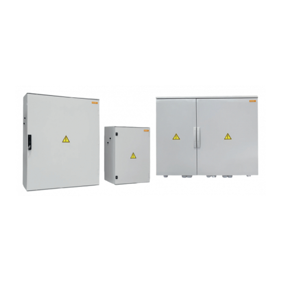
Figure 3.1 Product range 3.1 Product overview Parameters influencing the selection of the optimal PV DC COMBINER BOX is a complete range of tai- lor-made Level 1 combiner boxes for utility-scale photovol- PV DC COMBINER BOX taic systems. The combiner boxes are installed to join and –... - Page 7 Device description Figure 3.2 Main components of the PV DC COMBINER BOX (exam- ple) DC Switch String monitoring device Transclinic 16i+ (optional) Output DC+/- Ground terminal Fuse holders Input DC +/- (cable glands, alternatively WM4 C connectors) 4000001903/00/04.2020...
-
Page 8: Enclosure
Device description 3.2 Enclosure 3.4 Surge protection device (SPD) The enclosure of the PV DC COMBINER BOX is made of Glass Fibre Reinforced Polyester (GFRP). The en- closure provides IP65 and IK07 or higher in accordance with IEC 62208. Each enclosure is equipped with hinged door(s). -
Page 9: Fuses
Material damage! Only use fuses with silver plated end-caps. If you have to replace a fuse inside a PV DC COMBINER BOX, use the 3.9 Input terminals same type of fuses delivered with the original combiner box. -
Page 10: String Monitoring Device (Optional)
Device description 3.10 String monitoring device (optional) Figure 3.10 String monitoring device Transclinic 16i+ In case the PV DC COMBINER BOX is equipped with a string monitoring device, this device is a Transclinic 16i+ 1k5 HP with PUSH-IN terminals. This device simplifies the connection work inside the combiner box and reduces maintenance tasks due to the PUSH IN terminals. -
Page 11: General Technical Data
Device description 3.12 General technical data Main application features Inputs 8 to 32 Outputs 1 or 2 Operating ambient temperature range -20 ºC ... +50 ºC Rated DC voltage ≤ 1.000 V DC or ≤1.500 V DC Input connectors WM4 C connectors or cable glands Input connector technology Screw tied inputs (up to 16 mm cable) DC earthing system Floating, negative grounded or positive grounded system... -
Page 12: Transport And Storage
Transport and storage 4.1 Transporting 4.4 Establishing connections ATTENTION ► Always wear work shoes with foot protection when transporting and unpackage the combi- Material damage! ner box. The tension of the cables can cause mechanical stress to the enclosure. For this reason, depending on the instal- lation height, a strain relief underneath the combiner box ►... -
Page 13: Installation
5.2 Positioning of the combiner box caused by rodents. – Regard the permissible ambient conditions: The PV DC COMBINER BOX is designed to be installed – The temperature range is indicated on the label inside vertically with the cable glands or connectors leading down. -
Page 14: Fixation
Otherwise the cable glands Requirements and connectors at the bottom of the enclosure can be The PV DC COMBINER BOX shall be fixed to a suitable damaged. and stable metallic structure or a wall that will support the weight of the combiner box during the entire lifetime. - Page 15 Installation ► Check the installation: – Verify that the combiner box is correctly secured and fixed. – The surface of the enclosure should be totally flat. If the combiner box is bended over the edges, the tight- ness is not guaranteed. Figure 5.5 Fixing lugs enclosure type A Figure 5.6 Fixing lugs enclosure type B Each model has been designed according individual...
- Page 16 Installation Enclosures mounting lugs and fixing points Size Dimensions H x W x D (mm) 530 x 430 x 200 647 x 436 x 250 747 x 535 x 300 847 x 636 x 300 1056 x 853 x 362 1090 538 x 750 –...
- Page 17 Installation Enclosures mounting lugs and fixing points Size Dimensions H x W x D (mm) 735 x 535 x 270 835 x 635 x 300 1035 x 835 x 300 1080 PS 440 1000 x 1000 x 320 1060 PS 452 1000 x 1200 x 320 1260 1) This table is a reference. For specific measure of your product please refer to the documentation delivered with the product.
-
Page 18: Inserting The Fuses
The enclosure is equipped either with cable glands or with are two types of fuse holders that can be used in the PV connectors (WM4 C or PV stick). PV DC COMBINER BOX: In order to realise proper connections we recommend to – for 1000 V use wire end ferrules as well as appropriate stripping and –... -
Page 19: Connection Of The Outputs
The output connections depend on the design of each tailor-made PV DC COMBINER BOX. The output cables must be connected to the poles of the switch disconnector or to the terminals prepared for this purpose. Regard the delivered datasheet for the cable glands and a description of the clamping area. -
Page 20: Connection Of The Grounding Cable
5.8 Connection of the grounding cable The PV DC COMBINER BOX is designed without any me- tallic mounting plate or similar. The enclosure is made of GFRP (Glass Fiber Reinforced Polyester). Therefore the unique ground connector is used for the surge protection. -
Page 21: Connection Of The Communications (Optional)
Connection of the communications (optional) This section is needed if the combiner box contains a string ATTENTION monitoring device Transclinic 16i+ 1k5 HP (from now on Transclinic). This device has a communication port RS485. Material damage! The figure below shows how to connect multiple combiner RS485 wiring requires technical skills and tools different boxes in a master-slave configuration using RS485 con- to those available to regular electricians. -
Page 22: Wiring The Communications
6.1 Wiring the communications 6.2 Connecting the RS485 to the Transclinic DANGER By default, the PV DC COMBINER BOX with monitoring Imminent risk of life! comes with the internal communications pre-wired. This High voltages up to 1.000 or 1.500 V DC are means that there is a communication cable between the present in the live parts. - Page 23 Connection of the communications (optional) Please regard the following aspects when wiring the Damages to the RS485 transceiver IC of this RS485: equipment due to the following wiring errors will not be covered under warranty: – The RS485 bus topology must be a daisy chain (see –...
- Page 24 Connection of the communications (optional) The RS485 shields should be joined as shown below. WARNING Risk of electrical shock and product Transclinic 16i+ damage. RS485 Too short RS485 cables can cause mechani- cal strain to the equipment. D+ D– C ►...
-
Page 25: Configuration Of The Modbus Address And The Rs485 Serial Settings
Connection of the communications (optional) 6.3 Configuration of the Modbus address Changing the configuration and the RS485 serial settings To validate the change ID number, baud-rate or parity the process must be as it follows: The Modbus device address and the RS485 serial settings ►... -
Page 26: Recommendations When Configuring The Scada
Connection of the communications (optional) 6.5 Recommendations when configuring the SCADA If you will configurate the Scada or PLC acting as Modbus client please follow these recommendations: – The Modbus client timeout should be 1 second. – The practical polling interval per slave should be 20 sec- onds. -
Page 27: Commissioning
“Installation” chapter of this user manual. PV DC COMBINER BOX and the status of the installation. – The floor around the PV DC COMBINER BOX is firm The installation must comply with either local and interna- and easily accessible so that work can be done safe. -
Page 28: Start Up
Weidmüller representative for more information. ► Insert the fuses provided with the PV DC COMBINER BOX into the fuse holders using the appropiate tool from Weidmüller (or equivalent appropri- ated for this activity). ► Switch on the DC disconnection switch (from OFF to ON... -
Page 29: Accessories And Replacing Parts
Accessories and replacing parts 8.4 Replacing surge protection arresters Some parts of the PV DC COMBINER BOX can be replaced in case of damage. Before proceed with any of these replacements, we highly re- DANGER commend to contact with your Weidmüller repre- Imminent risk to life! sentative to clarify any doubt. - Page 30 Accessories and replacing parts Figure 8.3 Inserting a surge voltage arrester 4000001903/00/04.2020...
-
Page 31: Cleaning
► Use a cloth moistened with clear water for cleaning. ► Clean the PV DC COMBINER BOX at regular intervals so that the warning symbols are always clearly visible. ► Only clean the exterior of the enclosure when it is closed. -
Page 32: Maintenance And Service
► Ensure that the product is switched off and that it is free of hazardous voltage (from generator side and from inverter side). Check list for the annual inspection of the PV DC COMBINER BOX Remarks Issue Checked... -
Page 33: Service
Maintenance and Service Check list for the annual inspection of the PV DC COMBINER BOX Remarks Issue Checked Fuse holders Burn marks ► Check that there are no burn marks on the termi- nals. Measure voltage ► Check the voltage of the strings by using the test- ing points in the terminals. - Page 34 4000001903/00/04.2020...
Need help?
Do you have a question about the PV DC COMBINER BOX and is the answer not in the manual?
Questions and answers