Table of Contents
Advertisement
Quick Links
Advertisement
Table of Contents

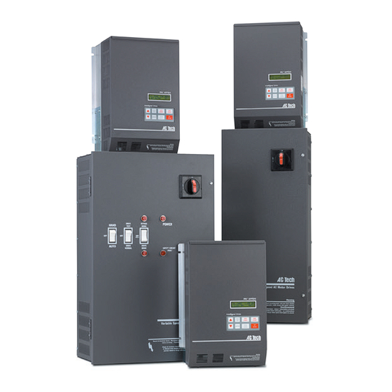
Summary of Contents for Lenze AC Tech MCH Series
- Page 1 MCH Series Drives Metasys N2 Communications Guide...
- Page 2 About These Instructions This documentation applies to the use of an MCH Series Variable Frequency Drive with Metasys N2 protocol and should be used in conjunction with the MCH Series Installation and Operation Manual (Document MH01) that shipped with the drive. These documents should be read in their entirety as they contain important technical data and describe the installation and operation of the drive.
-
Page 3: Table Of Contents
Contents 1 Safety Information ......................1 Warnings, Cautions and Notes ................1 1.1.1 General ....................1 1.1.2 Application ....................1 1.1.3 Installation ....................1 1.1.4 Electrical Connection ................2 1.1.5 Operation ....................2 2 Introduction ........................3 Metasys N2 Communications ................3 Serial Communications Wiring ................3 3 Drive Setup and Programming ...................4 Serial Communication Setup .................4 Communication Overrides ..................5 4 MCH N2 Points ........................6... -
Page 4: Safety Information
Safety Information Safety Information Warnings, Cautions and Notes 1.1.1 General Some parts of Lenze controllers (frequency inverters, servo inverters, DC controllers) can be live, moving and rotating. Some surfaces can be hot. Non-authorized removal of the required cover, inappropriate use, and incorrect installation or operation creates the risk of severe injury to personnel or damage to equipment. -
Page 5: Electrical Connection
Safety Information 1.1.4 Electrical Connection When working on live drive controllers, applicable national regulations for the prevention of accidents (e.g. VBG 4) must be observed. The electrical installation must be carried out in accordance with the appropriate regulations (e.g. cable cross-sections, fuses, PE connection). Additional information can be obtained from the regulatory documentation. -
Page 6: Introduction
8 data bits, no parity, 1 start bit and 1 stop bit. The bit sequence is as follows: DATA START STOP Serial Communications Wiring Figure 1 illustrates the MCH Series Terminal Strip and connections for the N2 Metasys network. 10A 10B 13B 13C 13D 14 Reference Figure 1: MCH Terminal Strip... -
Page 7: Drive Setup And Programming
Drive Setup & Programming Drive Setup and Programming Most drive parameters (including those required for serial communications) are not accessible through the N2 Network. They can only be accessed by entering the Programming Mode of the drive itself. Refer to the MCH Installation and Operation Manual (MH01) for more information. -
Page 8: Communication Overrides
Drive Setup & Programming 60 SERIAL TIMEOUT This parameter makes the serial watchdog timeout period selectable. It has a minimum value of 10 seconds and maximum value of 1800 seconds. The default value is 120 seconds. If no action is to be taken when a serial watchdog timeout occurs, Drive Parameter #57 (Serial) should be set to W/O TIMER. -
Page 9: Mch N2 Points
The MCH N2 Points are divided into four types: analog input, binary input, analog output and binary output. Sections 4.2 through 4.5 describe each of these point types and the individual point numbers within each. Metasys N2 Point Map Table 2: Metasys N2 Point Map for MCH Series Drives Point Point... -
Page 10: Analog Input (Ai) Point Descriptions
N2 Points Analog Input (AI) Point Descriptions Point Description 1-01: Actual Frequency This point represents the actual speed of the drive in Hz. 1-02: Command Frequency This point represents the commanded drive speed in Hz. 1-03: Load Percent This point represents the drive’s load current as a % of rated current. This value can also be seen on the local display. - Page 11 N2 Points Point Description 1-08: PID Setpoint Command This point is for monitoring the commanded PID Setpoint and is displayed in the drive’s internal PID units with a range of 0-32736. A value of 0 represents the lower of Drive Parameter #75 (Feedback @ Min) and Drive Parameter #76 (Feedback @ Max).
-
Page 12: Binary Input (Bi) Point Descriptions
N2 Points Binary Input (BI) Point Descriptions Point Description 2-01: PID Mode This point is for monitoring the general state of the drive’s PID mode. If Drive Parameter #70 (PID Mode) is set to OFF this point returns 0 (DISABLED). If Drive Parameter #70 is set to either NORMAL or REVERSE, then this point returns 1 (ENABLED). - Page 13 N2 Points Analog Output (AO) Point Descriptions Point Description 3-01: Acceleration Rate This point sets the time that it will take for the drive to ramp up the motor from 0.00Hz to the value set in Drive Parameter #18 (Base Frequency). It sets the value in Drive Parameter 8 (Accel Rate).
-
Page 14: Binary Output (Bo) Point Descriptions
Once the fault has been cleared, the value of this point will automatically return to NORMAL (0). Reference and Links MCH Series Variable Frequency Drives visit: http://www.lenze-actech.com Metasys N2 and Johnson Controls, Inc. visit: http://www.johnsoncontrols.com/publish/us/en/products/building_efficiency/building_ management/metasys.html... - Page 15 Lenze AC Tech Corporation 630 Douglas Street • Uxbridge MA 01569 • USA Sales: 800-217-9100 •Service: 508-278-9100 www.lenze-actech.com RG-MHMET-e6...


Need help?
Do you have a question about the MCH Series and is the answer not in the manual?
Questions and answers