Advertisement
Quick Links
Motherboard Components
40
1
2
3 4
41
39
33
38
37
35 34
36
32
45
44
43
42
31
30
29
46
47
28
CPU1
(Secondary)
27
26
23
25
24
22
PCI Express Card
4
1
2
3
Fan Duct
Hardware Installation Guide
1
SFP+ LAN port#1 Active LED
2
SFP+ LAN port #1 (Left)/SFP+ LAN port #2 (Right)
3
SFP+ LAN#2 link/Active LED
4
ID button with LED
5
6
12
5
GbE LAN port #1 (Left)/GbE LAN port #2 (Right)
6
VGA port
7
7
Serial port cable connector
8
Slimline connector #1 (PCIe x4 signal)
13
9
Slimline connector #2(PCIe x4 signal)
14
10
PCIe x 8 slot (Proprietary/for mezzanine card)
11
15
11
PCIe x 8 slot (Proprietary/for mezzanine card)
8
9
12
Sever management LAN port (top)/USB 3.0 ports (buttom)
13
Battery socket
16
14
PMBus connector
10
17
15
2x12 pin main power connector
18
16
System fan connector#5
19
17
CPU fan connector (for secondary CPU)
18
CPU fan connector (for primary CPU)
19
2x4 pin 12V power connector (for secondary CPU)
20
System fan connector#4
21
System fan connector#3
22
System fan connector#2
23
2x4 pin 12V power connector (for primary CPU)
24
System fan connector#1
25
SATA RAID upgrade key
26
LAN#4 Active LED
27
LAN#3 Active LED
28
Front panel header
29
Function jumper switch #2
30
Function jumper switch #1
31
Clear CMOS jumper
32
Error LED for DIMM slots
33
USB 3.0 header
34
Slimline connector #1 (SATA 6Gb/s signal/for SATA#0~#3)
21
20
Fan Module
3
35
Slimline connector #2 (SATA 6Gb/s signal/for SATA#4~#7)
36
Slimline connector #3 (SATA 6Gb/s signal/for sSATA#0~#3)
37
SATA 6Gb/s connector #5
38
SSATA DOM support power connector for SSATA port #5
39
TPM connector
40
BMC firmware readiness LED
41
IPMB connector
42
PCIe x16 slot #4 (Gen3 x16)
43
PCIe x16 slot #3 (Gen3 x16)
44
PCIe x16 slot #2 (Gen3 x16)
45
PCIe x16 slot #1 (Gen3 x16)
46
SATA 6Gb/s connector #4
47
SATA DOM support power connector for SSATA port #4
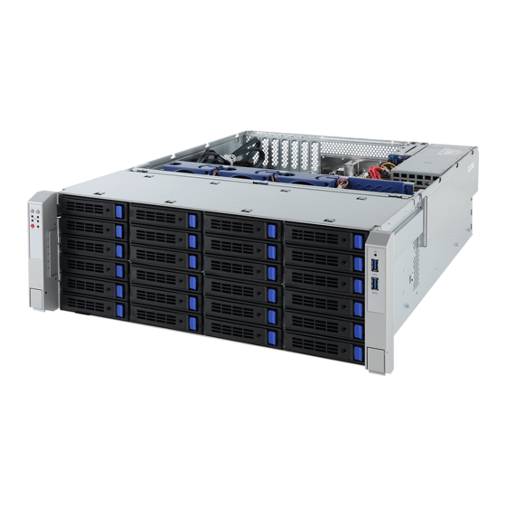
System Components
1
6
7
6
4
8
9
To replace the system fan
at the bottom:
No.
Description
1
PCIe Card Bays
2
2.5" Hard Drives
3
Power Supply Units
4
CPU1 DDR4 Memory
5
CPU1 with Heat Sink
6
CPU0 DDR4 Memory
7
CPU0 with Heat Sink
Jumper Settings
1
1
Clear
2
CMOS
3
CLR_CMOS
J1
2
HOST_SMBUS_SEL
1
2
PMBUS_SEL
2
3
S3_MASK
4
DB_PLD
J2
NOTE!
1
ME_UPDATE
Remove the system back cover before
2
BIOS_PWD
pulling out the tray
3
BIOS_RCVR
4
ME_RCVR
CPU/Heatsink
2
3
5
4
10
11
12
13
14
8
No.
Description
8
System Fan #1
9
System Fan #2
10
System Fan #3
11
System Fan #4
12
System Fan #5
13
System Fan #6
14
System Fan #7
Default
Enable
ON
OFF
BIOS defined
BIOS defined
BIOS defined
CPLD debug mode
Normal [Default]
ON
OFF
Force ME update
Normal [Default]
Clear supervisor password
Normal [Default]
BIOS recovery mode
Normal [Default]
ME recovery mode
Normal [Default]
PN.25LC2-D23330-L0R
1
2
3
10
4
7
9
Memory
Speed (MT/s); Voltage (V)
Slot Per Channel (SPC)
DIMM
DIMM Per Channel (DPC)
Capacity
Ranks Per
(GB)
1 Slot per
Type
DIMM and
2 Slot per Channel
Channel
Data Width
DIMM Density
1DPC
1DPC
4Gb
8Gb
1.2V
1.2V
RDIMM
SRx4
8GB
8GB
RDIMM
SRx8
4GB
16GB
RDIMM
DRx8
8GB
32GB
RDIMM
DRx4
16GB
2H 64GB
2666
2666
RDIMM
QRx4
N/A
64GB
3DS
LRDIMM
QRx4
N/A
2H 64GB
QRx4
N/A
LRDIMM
4H 128GB
3DS
8Rx4
N/A
2DPC
1.2V
2666
Advertisement

Related Manuals for Gigabyte S451-3R0


Summary of Contents for Gigabyte S451-3R0
- Page 1 Hardware Installation Guide PN.25LC2-D23330-L0R Motherboard Components CPU/Heatsink SFP+ LAN port#1 Active LED Slimline connector #2 (SATA 6Gb/s signal/for SATA#4~#7) SFP+ LAN port #1 (Left)/SFP+ LAN port #2 (Right) Slimline connector #3 (SATA 6Gb/s signal/for sSATA#0~#3) SFP+ LAN#2 link/Active LED SATA 6Gb/s connector #5 ID button with LED SSATA DOM support power connector for SSATA port #5 GbE LAN port #1 (Left)/GbE LAN port #2 (Right)
- Page 2 Hardware Quick Installation Guide CAUTION PN.25LC2-D93330-L0R System Overview Front Side LEDs and Buttons Rear Side TWO PERSON LIFT REQUIRED HDD1 HDD2 HDD3 HDD4 Firmly hold the bottom of the system when Secondary PSU HDD5 HDD6 HDD7 HDD8 Power Button with LED required to lift and carry the system.
Need help?
Do you have a question about the S451-3R0 and is the answer not in the manual?
Questions and answers