
Subscribe to Our Youtube Channel
Related Manuals for ProSoft MVI71-HART

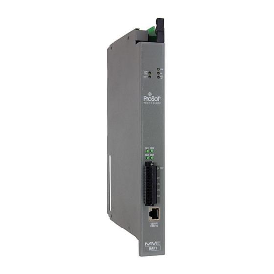
Summary of Contents for ProSoft MVI71-HART
- Page 1 MVI71-HART PLC Platform HART Multi-drop Master Communication Module October 7, 2020 USER MANUAL...
-
Page 2: Your Feedback Please
® ProSoft Technology Product Documentation In an effort to conserve paper, ProSoft Technology no longer includes printed manuals with our product shipments. User Manuals, Datasheets, Sample Ladder Files, and Configuration Files are provided at: www.prosoft-technology.com. For professional users in the European Union If you wish to discard electrical and electronic equipment (EEE), please contact your dealer or supplier for further information. -
Page 3: Important Installation Instructions
These products are intended to be mounted in an IP54 enclosure. The devices shall provide external means to prevent the rated voltage being exceeded by transient disturbances of more than 40%. This device must be used only with ATEX certified backplanes. DO NOT OPEN WHEN ENERGIZED. Page 3 of 146 ProSoft Technology, Inc. -
Page 4: Battery Life Advisory
CMOS setup and the real-time clock for approximately 21 days. When the battery is fully discharged, the module will revert to the default BIOS and clock settings. Note: The battery is not user replaceable. Page 4 of 146 ProSoft Technology, Inc. -
Page 5: Table Of Contents
MVI71-HART ♦ PLC Platform Index HART Multi-drop Master Communication Module User Manual Contents Your Feedback Please ........................2 How to Contact Us ..........................2 ® ProSoft Technology Product Documentation ................... 2 Important Installation Instructions ....................... 3 MVI (Multi Vendor Interface) Modules ....................3 Warnings ............................ - Page 6 Application Port Connection ................... 85 Example Field Terminations ................... 86 5.7.1 Notes ........................86 MVI71-HART Status Data Area and Error Codes ..........93 5.8.1 Protocol Error Codes ....................98 HART Universal Commands ................. 100 COMMAND 00 - Read Unique Identifier ................... 100 COMMAND 01 - Read Primary Variable ...................
- Page 7 MVI71-HART ♦ PLC Platform Start Here HART Multi-drop Master Communication Module User Manual COMMAND 51 - Write Dynamic Variable Assignments ............131 COMMAND 52 - Set Transmitter Variable Zero ................ 132 COMMAND 53 - Write Transmitter Variable Units ..............133 COMMAND 54 - Read Transmitter Variable Information ............
-
Page 8: Start Here
Hardware installation and wiring: install the module, and safely connect HART Multidrop and PLC devices to a power source and to the MVI71-HART module’s application port(s) System Requirements The MVI71-HART module requires the following minimum hardware and software components: ... -
Page 9: Package Contents
HART Multi-drop Master Communication Module User Manual Package Contents The following components are included with your MVI71-HART module, and are all required for installation and configuration. Important: Before beginning the installation, please verify that all of the following items are present. -
Page 10: Install The Module In The Rack
After you have checked the placement of the jumpers, insert MVI71-HART into the PLC™ chassis. Use the same technique recommended by Rockwell Automation to remove and install PLC modules. -
Page 11: Connect Your Pc To The Processor
MVI71-HART ♦ PLC Platform Start Here HART Multi-drop Master Communication Module User Manual Connect your PC to the Processor Connect the right-angle connector end of the cable to your controller at the communications port. Connect the straight connector end of the cable to the serial port on your computer. -
Page 12: Download The Sample Program To The Processor
MVI71-HART ♦ PLC Platform Start Here HART Multi-drop Master Communication Module User Manual Download the Sample Program to the Processor To download the sample program from RSLogix 5 to the PLC processor: Note: The key switch on the front of the PLC processor must be in the REM position. -
Page 13: Configuring The Rslinx Driver For The Pc Com Port
MVI71-HART ♦ PLC Platform Start Here HART Multi-drop Master Communication Module User Manual When the download is complete, RSLogix will open another confirmation dialog box. Click OK to switch the processor from Program mode to Run mode. Note: If you receive an error message during these steps, refer to your RSLogix documentation to interpret and correct the error. -
Page 14: Connecting Your Pc To The Module
With the module securely mounted, connect your PC to the Configuration/Debug port using the RJ45-DB-9 Serial Adapter Cable and the Null Modem Cable included in the package with the MVI71-HART module. Connect the RJ45-DB-9 Serial Adapter Cable to the Null Modem Cable. -
Page 15: Module Configuration
Configuration File................... 18 This section contains the setup procedure, data, and ladder logic for successful application of the MVI71-HART module. Each step in the setup procedure is defined in order to simplify the use of the module. Page 15 of 146... -
Page 16: Installing And Configuring The Module
Modify the module’s configuration files to meet the needs of your application, and copy the updated configuration to the module. Example configuration files are provided at: www.prosoft-technology.com. Refer to the Modifying the Example Configuration File section, later in this chapter, for more information on the configuration files. -
Page 17: Module Data
User Manual Module Data All data related to the MVI71-HART module is stored in a user defined data files. It is the responsibility of the ladder logic programmer to construct all the data files required by the program and to write the ladder logic required to interface to these files. The ladder logic is also responsible for transferring floating-point data between the files used for data transfer (integer files) and floating-point files. -
Page 18: Configuration File
MVI71-HART ♦ PLC Platform Module Configuration HART Multi-drop Master Communication Module User Manual Configuration File In order for the module to operate, a configuration file (HART.CFG) is required. This configuration file contains all the information required to configure the module's master drivers and establish a command list for each port. -
Page 19: Module]
Write Block IDs (1000 to 1067). The ladder logic is required to update the last data in the PLC memory to the MVI71-HART module. The number of blocks transferred is based on how the ReadData register count is setup in the module definition parameters of the loaded configuration file. -
Page 20: Hart Port X]
MVI71-HART ♦ PLC Platform Module Configuration HART Multi-drop Master Communication Module User Manual 2.3.2 [HART PORT x] The [HART PORT x] sections of the configuration file set the HART channel communication parameters, define the protocol specifics and set the command list parameters. - Page 21 MVI71-HART ♦ PLC Platform Module Configuration HART Multi-drop Master Communication Module User Manual Slave List Status The configuration parameter "DB Address Status" defines the register address in the virtual database where the status data for each HART channel will be placed. This word has one bit for each HART device and if this bit is in "1"...
- Page 22 MVI71-HART ♦ PLC Platform Module Configuration HART Multi-drop Master Communication Module User Manual Auto-Poll Swap Float 0 to 3 This parameter swaps the floating-point data values received by the auto-poll feature. Swap Code Description None - No Change is made in the byte ordering (1234 = 1234) Words - The words are swapped (1234=3412) Words &...
-
Page 23: Hart Port X Commands]
HART channels. The module supports up to 100 commands per channel. Command List Overview The MVI71-HART module uses a command list to interface with HART slave devices. The commands in the list specify: the slave device to be addressed ... - Page 24 MVI71-HART ♦ PLC Platform Module Configuration HART Multi-drop Master Communication Module User Manual Commands Supported by the Module The format of each command in the list is independent on the function being executed. All parameters in the command table must be entered. Only one parameter is optional, the Fixed Data field, which contains data to be sent to a HART device.
- Page 25 MVI71-HART ♦ PLC Platform Module Configuration HART Multi-drop Master Communication Module User Manual Command Definition Trim DAC Zero Trim DAC Gain Write Transfer Function Read Additional Transmitter Status Write PV Sensor Serial Number Read Dynamic Variable Assignments Write Dynamic Variable Assignments...
- Page 26 This value is valid only when there is a specified "Write DB Address" (see below) with a non-zero byte count for write commands. The HART module will send the command if either the MVI71-HART module OR the HART device is powered up. This is mainly used for configuration of HART devices on startup.
- Page 27 MVI71-HART ♦ PLC Platform Module Configuration HART Multi-drop Master Communication Module User Manual FP Word Count -1 to 125 This parameter specifies the number of words from the floating point data returned by a HART command that will be placed on the Virtual Database. If this parameter is 0 no data will be written to the Database.
- Page 28 MVI71-HART ♦ PLC Platform Module Configuration HART Multi-drop Master Communication Module User Manual Int Word Count 0 to 125 This parameter specifies the number of words from the integer or packed ASCII string data returned by a HART command that will be placed on the Virtual Database. If this parameter is "0", no data will be written to the Database.
- Page 29 MVI71-HART ♦ PLC Platform Module Configuration HART Multi-drop Master Communication Module User Manual Write DB Address -1 to 3999 This field specifies the internal database register to be as a source of data for HART command which includes data. It is possible to include data with every HART command, but it depends of the command and of the device if it will accept this data.
-
Page 30: Hart Command Examples
MVI71-HART ♦ PLC Platform Module Configuration HART Multi-drop Master Communication Module User Manual 2.3.4 Hart Command Examples This section describes two examples that shows how to configure HART commands. The first example shows a read command (function code 3 - READ DYNAMIC VARIABLES) and the second example shows a write command (function 34 - WRITE DAMPING VALUE). - Page 31 MVI71-HART ♦ PLC Platform Module Configuration HART Multi-drop Master Communication Module User Manual Index Parameter Value Observation Short This command is sent to the Hart slave device Address using short address 0 Function The command function 3 (READ DYNAMIC Code VARIABLES) is used in this example Int.
- Page 32 MVI71-HART ♦ PLC Platform Module Configuration HART Multi-drop Master Communication Module User Manual Example of HART Command Function 34 The following example shows how to configure a command function 34 (WRITE DAMPING VALUE) to write a damping values (seconds) to the HART slave device.
-
Page 33: Uploading And Downloading The Configuration File
2.3.5 Uploading and Downloading the Configuration File ProSoft modules are shipped with a pre-loaded configuration file. In order to edit this file, you may transfer the file from the module to your PC. After editing, you must transfer the file back to the module for your changes to take effect. - Page 34 Microsoft Windows operating systems. If you are connecting from a machine running DOS, you must obtain and install a compatible communication program. The following table lists communication programs that have been tested by ProSoft Technology. ProComm, as well as several other terminal emulation programs Windows 3.1...
- Page 35 MVI71-HART ♦ PLC Platform Module Configuration HART Multi-drop Master Communication Module User Manual In the Receive File dialog box, browse to the location on your PC where the configuration file should be stored, and select Zmodem as the receiving protocol.
- Page 36 MVI71-HART ♦ PLC Platform Module Configuration HART Multi-drop Master Communication Module User Manual The configuration file is now on your PC at the location you specified. You can now open and edit the file in a text editor such as Windows Notepad. When you have finished editing the file, save it and close Notepad.
- Page 37 MVI71-HART ♦ PLC Platform Module Configuration HART Multi-drop Master Communication Module User Manual Transferring the Configuration File to the Module Perform the following steps to transfer a configuration file from your PC to the module. Connect your PC to the Configuration/Debug port of the module using a terminal program such as HyperTerminal.
- Page 38 MVI71-HART ♦ PLC Platform Module Configuration HART Multi-drop Master Communication Module User Manual From the Transfer menu in HyperTerminal, select Send File. The Send File dialog appears. Use the Browse button to locate the configuration file your computer. Note: This procedure assumes that you are transferring a newly edited configuration file from your PC to the module.
- Page 39 MVI71-HART ♦ PLC Platform Module Configuration HART Multi-drop Master Communication Module User Manual Click the Send button. This action opens the Zmodem File Send dialog box. When the transfer is complete, the screen indicates that the module has reloaded program values and displays information about the module.
-
Page 40: Ladder Logic
User Manual Ladder Logic Ladder logic is required for the MVI71-HART module to operate. Tasks that must be handled by the ladder logic are module data transfer, special block handling, and status data receipt. Additionally, a power-up handler may be needed to handle the initialization of the module’s data and to clear any processor fault conditions. -
Page 41: Diagnostics And Troubleshooting
Status data contained in the module can be viewed through the Configuration/Debug port, using the troubleshooting and diagnostic capabilities of ProSoft Configuration Builder (PCB). Status data values can be transferred from the module to processor memory and can be monitored there manually or by customer-created logic. -
Page 42: Reading Status Data From The Module
HART Multi-drop Master Communication Module User Manual Reading Status Data from the Module The MVI71-HART module returns a status data set to the PLC processor in read blocks with identification codes of 0 and -1. This data is transferred to the PLC processor continuously. -
Page 43: Required Software
Microsoft Windows operating systems. If you are connecting from a machine running DOS, you must obtain and install a compatible communication program. The following table lists communication programs that have been tested by ProSoft Technology. ProComm, as well as several other terminal emulation programs Windows 3.1... -
Page 44: Using The Configuration/Debug Port
On computers with more than one serial port, verify that your communication program is connected to the same port that is connected to the module. If you are still not able to establish a connection, you can contact ProSoft Technology Technical Support for further assistance. - Page 45 MVI71-HART ♦ PLC Platform Diagnostics and Troubleshooting HART Multi-drop Master Communication Module User Manual Viewing Block Transfer Statistics Press [B] from the Main menu to view the Block Transfer Statistics screen. Use this command to display the configuration and statistics of the backplane data transfer operations between the module and the processor.
-
Page 46: Hart Master Menu
MVI71-HART ♦ PLC Platform Diagnostics and Troubleshooting HART Multi-drop Master Communication Module User Manual Transferring the Configuration File from The Module to the PC On the Diagnostics Menu this is referred to as Send Module Configuration. Press [S] to send (upload) the configuration file from the module to your PC. - Page 47 MVI71-HART ♦ PLC Platform Diagnostics and Troubleshooting HART Multi-drop Master Communication Module User Manual Opening the Data Analyzer Menu Press [A] to open the Data Analyzer Menu. Use this command to view all bytes of data transferred on each port. Both the transmitted and received data bytes are displayed.
- Page 48 MVI71-HART ♦ PLC Platform Diagnostics and Troubleshooting HART Multi-drop Master Communication Module User Manual Viewing Port Status and Configuration Press [1], [2], [3], or [4] to view status and configuration for ports 0 through 3 respectively. HART Error Descriptions Error Type...
-
Page 49: Data Analyzer
MVI71-HART ♦ PLC Platform Diagnostics and Troubleshooting HART Multi-drop Master Communication Module User Manual 4.1.6 Data Analyzer The data analyzer mode allows you to view all bytes of data transferred on each port. Both the transmitted and received data bytes are displayed. Use of this feature is limited without a thorough understanding of the protocol. - Page 50 MVI71-HART ♦ PLC Platform Diagnostics and Troubleshooting HART Multi-drop Master Communication Module User Manual Displaying Timing Marks in the Data Analyzer You can display timing marks for a variety of intervals in the data analyzer screen. These timing marks can help you determine communication-timing characteristics.
- Page 51 MVI71-HART ♦ PLC Platform Diagnostics and Troubleshooting HART Multi-drop Master Communication Module User Manual Starting the Data Analyzer Press [B] to start the data analyzer. After the key is pressed, all data transmitted and received on the currently selected port will be displayed. The following illustration shows an example.
-
Page 52: Data Analyzer Tips
MVI71-HART ♦ PLC Platform Diagnostics and Troubleshooting HART Multi-drop Master Communication Module User Manual 4.1.7 Data Analyzer Tips From the main menu, press [A] for the "Data Analyzer". You should see the following text appear on the screen: After the "Data Analyzer" mode has been selected, press [?] to view the Data Analyzer menu. - Page 53 User Manual Next name the file, and select a directory to store the file in. In this example, we are creating a file ProSoft.txt and storing this file on our root C: drive. After you have done this, press the button.
-
Page 54: Master Command Error List Menu
MVI71-HART ♦ PLC Platform Diagnostics and Troubleshooting HART Multi-drop Master Communication Module User Manual 4.1.8 Master Command Error List Menu Use this menu to view the command error list for the module. Press [?] to view a list of commands available on this menu. -
Page 55: Master Command List Menu
MVI71-HART ♦ PLC Platform Diagnostics and Troubleshooting HART Multi-drop Master Communication Module User Manual 4.1.9 Master Command List Menu Use this menu to view the command list for the module. Press [?] to view a list of commands available on this menu. -
Page 56: Led Status Indicators
The battery voltage is low or battery is not present. Allow battery to charge by keeping module plugged into rack for 24 hours. If BAT LED still does not go off, contact ProSoft Technology, as this is not a user serviceable item. -
Page 57: Troubleshooting
HART Multi-drop Master Communication Module User Manual 4.2.1 Troubleshooting Use the following troubleshooting steps if you encounter problems when the module is powered up. If these steps do not resolve your problem, please contact ProSoft Technology Technical Support. Processor Errors Problem description... -
Page 58: Reference
DB9 to RJ45 Adaptor (Cable 14) ............84 Application Port Connection ..............85 Example Field Terminations ..............86 MVI71-HART Status Data Area and Error Codes ........93 HART Universal Commands ..............100 HART Common Practice Commands ..........113 Page 58 of 146... -
Page 59: Product Specifications
(5000 registers maximum). The MVI71-HART module is the perfect solution for industrial applications in chemical and refining operations, gas and liquid distribution systems, and remote offshore monitoring stations, addressing virtually all aspects of control, data acquisition, and maintenance. -
Page 60: Hardware Specifications
Protocol Supported: HART protocol uses the Bell 202 standard frequency shift-keying (FSK) digital signal to communicate at 1200 baud, superimposed at a low level on the 4 to 20mA analog measurement signal. The MVI71-HART module supports version 5 of the HART protocol. - Page 61 MVI71-HART ♦ PLC Platform Reference HART Multi-drop Master Communication Module User Manual Supported Function Codes: HART Universal Commands Set supported are 00 to 03, 06 to 09, and 11 to 22. HART Common Practice Commands Set supported are 33 to 83 and 105 to 110.
-
Page 62: Functional Overview
MVI71-HART ♦ PLC Platform Reference HART Multi-drop Master Communication Module User Manual Functional Overview 5.2.1 General Concepts The following discussion explains several concepts that are important for understanding module operation. Module Power Up On power up, the module begins performing the following logical functions:... -
Page 63: Backplane Data Transfer
User Manual 5.2.2 Backplane Data Transfer The MVI71-HART module communicates directly over the PLC backplane for the block transfer interface. Data is paged between the module and the PLC processor across the backplane using BTR and BTW operations. Data is transferred from the module to the processor using the BTR blocks, and data is transferred from the processor to the module using the BTW blocks. - Page 64 Data contained in this database is paged through the block transfer interface by coordination of the PLC ladder logic and the MVI71-HART module's program. Up to 64 words of data can be transferred from the module to the processor at a time. Up to 64 words of data can be transferred from the processor to the module.
-
Page 65: Normal Data Transfer
MVI71-HART ♦ PLC Platform Reference HART Multi-drop Master Communication Module User Manual The configuration would set up the following backplane usage: 5.2.3 Normal Data Transfer Normal data transfer includes the transferring of data received by, or to be transmitted to, the master drivers and the status data. These data are transferred through read and write blocks. -
Page 66: Command Control Blocks
This information can be used to determine the "health" and activity of the module. Refer to MVI71-HART Status Data Area and Error Codes (page 93) for a detailed listing of the area and its contents. - Page 67 MVI71-HART ♦ PLC Platform Reference HART Multi-drop Master Communication Module User Manual Block Response Offset Description Length 1000 to 1066 1 to 60 Data to place in database 61 to 63 Not Used For example, for a Read Data Area of 2 blocks (120 words), blocks 1000 and 1001 would be used.
- Page 68 MVI71-HART ♦ PLC Platform Reference HART Multi-drop Master Communication Module User Manual Block 9903: Command Disable Control Block The block 9903 identification code is used by the processor to disable a set of commands that have an enable code set to 4 or 5 (one shot). The value referenced by the address associated with the command, Enable DB Address, will be set to 0 to disable the command.
- Page 69 MVI71-HART ♦ PLC Platform Reference HART Multi-drop Master Communication Module User Manual Word Offset in Block Data Field(s) Description Block ID This is the next block requested by the module. Port Number This field contains the port number (0 to 3) corresponding to the data contained in the block.
-
Page 70: Hart Channels
User Manual 5.2.5 HART Channels The MVI71-HART module supports the HART protocol as a Master on up to 4 channels. Each channel is individually configurable. The relationship between the port labeling on the front of the module and the application... - Page 71 The module does all this processing of the address automatically. In a HART network, it is possible to have two masters. The MVI71-HART module fully supports the existence of a second master, but it can reduce the throughput on the HART network.
- Page 72 MVI71-HART ♦ PLC Platform Reference HART Multi-drop Master Communication Module User Manual Auto-Poll Modes Each HART channel can be set to operate in three different modes: Point-to-Point Multi-drop User Mode Using the configuration file, choose the auto-poll mode through the Auto-Poll Code parameter (P, M, or N).
-
Page 73: Master Driver
MVI71-HART ♦ PLC Platform Reference HART Multi-drop Master Communication Module User Manual 5.2.6 Master Driver The master driver supported on each application port of the module emulates a HART master device. Configuration of each port is independent and should be connected to different HART networks. -
Page 74: Auto-Polling
MVI71-HART ♦ PLC Platform Reference HART Multi-drop Master Communication Module User Manual For all commands, it is possible to select where the Write Data comes from; it can be in the module’s internal database or it can be configured as a fixed data block in the command. - Page 75 MVI71-HART ♦ PLC Platform Reference HART Multi-drop Master Communication Module User Manual If the unit is set for point-to-point mode, the module will automatically gather the information for the device with the polling address (short address) of zero and place the data into the database.
- Page 76 MVI71-HART ♦ PLC Platform Reference HART Multi-drop Master Communication Module User Manual DB Byte Type Description Byte Data Use of Data Offset Source TOTAL BYTE COUNT TOTAL WORD COUNT DB Byte Type Description Byte Data Use of Data Offset Source...
- Page 77 MVI71-HART ♦ PLC Platform Reference HART Multi-drop Master Communication Module User Manual Auto-Poll Disabled Mode If the auto-polling feature is disabled (Auto-Poll Code = N), the module functions as shown in the following diagram: Only the user commands are executed and all data is placed in and sourced from the module's internal database.
- Page 78 MVI71-HART ♦ PLC Platform Reference HART Multi-drop Master Communication Module User Manual When the point-to-point mode of auto-polling is enabled (Auto-Poll Code = P), the following diagram applies to the channel operation: Page 78 of 146 ProSoft Technology, Inc.
- Page 79 MVI71-HART ♦ PLC Platform Reference HART Multi-drop Master Communication Module User Manual Multi-drop Mode Important: If the HART device address is between 1 and 15, you must configure the channel for multi-drop mode. If the unit is set for multi-drop mode, the module will poll each unit attached to the channel starting with polling address 1.
- Page 80 MVI71-HART ♦ PLC Platform Reference HART Multi-drop Master Communication Module User Manual If the module is configured for multi-drop auto-polling (Auto-Poll Code = M), the following diagram applies: In multi-drop mode, the channel will poll for instruments 1 to the value set in the MAX DEVICE COUNT parameter.
- Page 81 MVI71-HART ♦ PLC Platform Reference HART Multi-drop Master Communication Module User Manual Multi-drop Mode Example: The intent is to show when using Multi-drop mode how the Auto-Poll DB Address and Max Device Count parameters should be used. If the configuration file sets the following parameters:...
-
Page 82: Disabling The Rslinx Driver For The Com Port On The Pc
The communication port driver in RSLinx can occasionally prevent other applications from using the PC’s COM port. If you are not able to connect to the module’s configuration/debug port using ProSoft Configuration Builder (PCB), HyperTerminal or another terminal emulator, follow these steps to disable the RSLinx driver. - Page 83 MVI71-HART ♦ PLC Platform Reference HART Multi-drop Master Communication Module User Manual If you see the status as running, you will not be able to use this com port for anything other than communication to the processor. To stop the driver press the S...
-
Page 84: Configuration/Debug Port
MVI71-HART ♦ PLC Platform Reference HART Multi-drop Master Communication Module User Manual RS-232 Configuration/Debug Port This port is physically an RJ45 connection. An RJ45 to DB-9 adapter cable is included with the module. This port permits a PC-based terminal emulation program to view configuration and status data in the module and to control the module. -
Page 85: Application Port Connection
HART Multi-drop Master Communication Module User Manual Application Port Connection The MVI71-HART module has a single terminal connector to attach the module to the HART networks. Refer to Example Field Terminations (page 86) for diagrams displaying different field termination examples. -
Page 86: Example Field Terminations
MVI71-HART ♦ PLC Platform Reference HART Multi-drop Master Communication Module User Manual Example Field Terminations Up to 15 One instrument per channel instruments per channel Multi-drop Mode Point to Point Point to Point Mode Mode with (address 1 to 15) - Page 87 MVI71-HART ♦ PLC Platform Reference HART Multi-drop Master Communication Module User Manual For multi-drop applications, the 1K resistor should be normally used when one transmitter is connected to the port. If you increase the number of devices connected to a single port, you may need to reduce the size of the resistor.
- Page 88 MVI71-HART ♦ PLC Platform Reference HART Multi-drop Master Communication Module User Manual Page 88 of 146 ProSoft Technology, Inc.
- Page 89 MVI71-HART ♦ PLC Platform Reference HART Multi-drop Master Communication Module User Manual Page 89 of 146 ProSoft Technology, Inc.
- Page 90 MVI71-HART ♦ PLC Platform Reference HART Multi-drop Master Communication Module User Manual Page 90 of 146 ProSoft Technology, Inc.
- Page 91 MVI71-HART ♦ PLC Platform Reference HART Multi-drop Master Communication Module User Manual Page 91 of 146 ProSoft Technology, Inc.
- Page 92 MVI71-HART ♦ PLC Platform Reference HART Multi-drop Master Communication Module User Manual Page 92 of 146 ProSoft Technology, Inc.
-
Page 93: Mvi71-Hart Status Data Area And Error Codes
Reference HART Multi-drop Master Communication Module User Manual MVI71-HART Status Data Area and Error Codes This section contains a listing of the data contained in the MVI71-HART status data object, configuration error word and module error codes. Offset Content Description... - Page 94 MVI71-HART ♦ PLC Platform Reference HART Multi-drop Master Communication Module User Manual Offset Content Description Channel 1 Device Poll List Each bit in this word corresponds to a slave address (bit mapped) on the network starting at bit 1 for slave address 1. Bit 0 is not used.
- Page 95 MVI71-HART ♦ PLC Platform Reference HART Multi-drop Master Communication Module User Manual Offset Content Description Channel 2 Command This field contains the total number of request Request Count messages issued on the Channel. Channel 2 Command This field contains the total number of response Response Count messages received from devices on the network.
- Page 96 MVI71-HART ♦ PLC Platform Reference HART Multi-drop Master Communication Module User Manual Offset Content Description Channel 4 State Channel 4 state machine value (used for debugging) Polling Config Data Poll User Poll Wait Unique ID Comm State Channel 4 communication state machine value (used...
- Page 97 MVI71-HART ♦ PLC Platform Reference HART Multi-drop Master Communication Module User Manual Code Description 0x0008 Invalid Preambles (1 to 50) 0x0010 Invalid Short Address Retries (0 to 50) 0x0020 Invalid Long Address Retries (0 to 50) 0x0040 Invalid Retries After Error (0 to 50)
-
Page 98: Protocol Error Codes
MVI71-HART ♦ PLC Platform Reference HART Multi-drop Master Communication Module User Manual 5.8.1 Protocol Error Codes These are error codes that are part of the HART protocol. The standard HART error codes are shown in the following tables: Error Code Word... - Page 99 MVI71-HART ♦ PLC Platform Reference HART Multi-drop Master Communication Module User Manual BIT 7 OF FIRST BYTE = 0 COMMAND ERROR BIT 2 Analog Output Saturated BIT 1 Variable (Not Primary) Out of Limits BIT 0 Primary Variable Out of Limits...
-
Page 100: Hart Universal Commands
MVI71-HART ♦ PLC Platform Reference HART Multi-drop Master Communication Module User Manual HART Universal Commands COMMAND 00 - Read Unique Identifier Description This command gets the long address of the HART device plus other manufacturer information like Manufacturer ID, Device Type Code, Software Revision, Hardware Revision, and so on. -
Page 101: Command 01 - Read Primary Variable
MVI71-HART ♦ PLC Platform Reference HART Multi-drop Master Communication Module User Manual COMMAND 01 - Read Primary Variable Description This command gets the device Primary Variable and the Primary Variable Units Write Parameters NONE Floating Point Data Returned Word High Byte... -
Page 102: Command 02 - Read Current And Percent Of Range
MVI71-HART ♦ PLC Platform Reference HART Multi-drop Master Communication Module User Manual COMMAND 02 - Read Current And Percent Of Range Description This command gets the current of the loop that is forced by the HART device and the Percent of Range of the Current. -
Page 103: Command 03 - Read Dynamic Variables
MVI71-HART ♦ PLC Platform Reference HART Multi-drop Master Communication Module User Manual COMMAND 03 - Read Dynamic Variables Description This command gets the current and four (predefined) dynamic Variables. Write Parameters NONE Floating Point Data Returned Word High Byte Low Byte... -
Page 104: Command 06 - Write Polling Address
MVI71-HART ♦ PLC Platform Reference HART Multi-drop Master Communication Module User Manual COMMAND 06 - Write Polling Address Description This command sets the polling address of a HART device. Extreme care should be taken when you use this command because you can loose the communication with the device. -
Page 105: Command 12 - Read Message
MVI71-HART ♦ PLC Platform Reference HART Multi-drop Master Communication Module User Manual COMMAND 12 - Read Message Description This command reads an ASCII message contained in the HART Device and written by the Write Message command 17. Write Parameters NONE... -
Page 106: Command 13 - Read Tag, Descriptor And Date
MVI71-HART ♦ PLC Platform Reference HART Multi-drop Master Communication Module User Manual COMMAND 13 - Read Tag, Descriptor and Date Description This command reads an ASCII Tag which identifies the device, an ASCII descriptor of the device and the last Date it has been configured. -
Page 107: Command 14 - Read Pv Sensor Info
MVI71-HART ♦ PLC Platform Reference HART Multi-drop Master Communication Module User Manual COMMAND 14 - Read PV Sensor Info Description This command gets information about the Primary Variable sensor, like limits and span. Write Parameters NONE Floating Point Data Returned... -
Page 108: Command 15 - Read Output Information
MVI71-HART ♦ PLC Platform Reference HART Multi-drop Master Communication Module User Manual COMMAND 15 - Read Output Information Description This command gets information about the Primary Variable Output Information. Write Parameters NONE Floating Point Data Returned Word High Byte Low Byte... -
Page 109: Command 16 - Read Final Assembly Number
MVI71-HART ♦ PLC Platform Reference HART Multi-drop Master Communication Module User Manual COMMAND 16 - Read Final Assembly Number Description This command reads the final assembly number of the HART device. Write Parameters NONE Floating Point Data Returned NONE Integer Data Returned... -
Page 110: Command 17 - Write Message
MVI71-HART ♦ PLC Platform Reference HART Multi-drop Master Communication Module User Manual COMMAND 17 - Write Message Description This command writes an ASCII message contained in the HART Device and that can be read with command 12. Write Parameters Word... -
Page 111: Command 18 - Write Tag, Descriptor And Date
MVI71-HART ♦ PLC Platform Reference HART Multi-drop Master Communication Module User Manual COMMAND 18 - Write Tag, Descriptor and Date Description This command writes an ASCII Tag which identifies the device, an ASCII descriptor of the device and the last Date it has been configured. -
Page 112: Command 19 - Write Final Assembly Number
MVI71-HART ♦ PLC Platform Reference HART Multi-drop Master Communication Module User Manual COMMAND 19 - Write Final Assembly Number Description This command writes the final assembly number of the HART device. Write Parameters Word High Byte Low Byte Final Assembly Number 0... -
Page 113: Hart Common Practice Commands
MVI71-HART ♦ PLC Platform Reference HART Multi-drop Master Communication Module User Manual 5.10 HART Common Practice Commands COMMAND 33 - Read Transmitter Variables Description This command gets four user selected dynamic Variables. Write Parameters Word High Byte Low Byte Transmitter Variable Code For Slot 0... -
Page 114: Command 34 - Write Damping Value
MVI71-HART ♦ PLC Platform Reference HART Multi-drop Master Communication Module User Manual COMMAND 34 - Write Damping Value Description This command writes the damping value of a HART device. Write Parameters Word High Byte Low Byte Floating Point Damping Value (Sec) -
Page 115: Command 35 - Write Range Values
MVI71-HART ♦ PLC Platform Reference HART Multi-drop Master Communication Module User Manual COMMAND 35 - Write Range Values Description This command writes the Upper and Lower range of the Primary Variable Write Parameters Word High Byte Low Byte Range Units Code... -
Page 116: Command 36 - Set Upper Range Value
MVI71-HART ♦ PLC Platform Reference HART Multi-drop Master Communication Module User Manual COMMAND 36 - Set Upper Range Value Description This command is similar in effect to push the SPAN button of the HART device but doing it remotely through the HART network. -
Page 117: Command 37 - Set Lower Range Value
MVI71-HART ♦ PLC Platform Reference HART Multi-drop Master Communication Module User Manual COMMAND 37 - Set Lower Range Value Description This command is similar in effect to push the ZERO button of the HART device but doing it remotely through the HART network. -
Page 118: Command 38 - Reset Configuration Changed Flag
MVI71-HART ♦ PLC Platform Reference HART Multi-drop Master Communication Module User Manual COMMAND 38 - Reset Configuration Changed Flag Description This command resets the status bit that indicates that configuration has been changed. Write Parameters NONE Floating Point Data Returned... -
Page 119: Command 39 - Eeprom Control
MVI71-HART ♦ PLC Platform Reference HART Multi-drop Master Communication Module User Manual COMMAND 39 - EEPROM Control Description This command operates over the EEPROM changing its settings. Write Parameters Word High Byte Low Byte EEPROM Control Code EEPROM Control Code... -
Page 120: Command 40 - Enter Exit Fixed Current Mode
MVI71-HART ♦ PLC Platform Reference HART Multi-drop Master Communication Module User Manual COMMAND 40 - Enter Exit Fixed Current Mode Description This command writes the damping value of a HART device. Write Parameters Word High Byte Low Byte Floating Point Current (mA) -
Page 121: Command 41 - Perform Transmitter Self Test
MVI71-HART ♦ PLC Platform Reference HART Multi-drop Master Communication Module User Manual COMMAND 41 - Perform Transmitter Self Test Description This command starts the HART device Self Test to find if there is any problem with the device hardware. Write Parameters... -
Page 122: Command 42 - Perform Master Reset
MVI71-HART ♦ PLC Platform Reference HART Multi-drop Master Communication Module User Manual COMMAND 42 - Perform Master Reset Description This command performs a master reset in the HART device. Write Parameters NONE Floating Point Data Returned NONE Integer Data Returned... -
Page 123: Command 43 - Set Pv Zero
MVI71-HART ♦ PLC Platform Reference HART Multi-drop Master Communication Module User Manual COMMAND 43 - Set PV Zero Description This command forces the Primary Value to Zero. Write Parameters NONE Floating Point Data Returned NONE Integer Data Returned Word High Byte... -
Page 124: Command 44 - Write Pv Units
MVI71-HART ♦ PLC Platform Reference HART Multi-drop Master Communication Module User Manual COMMAND 44 - Write PV Units Description This command changes the setting of the Primary Variable units. Write Parameters Word High Byte Low Byte Primary Variable Units Code... -
Page 125: Command 45 - Trim Dac Zero
MVI71-HART ♦ PLC Platform Reference HART Multi-drop Master Communication Module User Manual COMMAND 45 - Trim DAC Zero Description This command calibrates the device Digital to analog converter zero. This is done by writing the same current value that is measured in the loop. -
Page 126: Command 46 - Trim Dac Gain
MVI71-HART ♦ PLC Platform Reference HART Multi-drop Master Communication Module User Manual COMMAND 46 - Trim DAC Gain Description This command calibrates the device Digital to analog converter gain. This is done by writing the same current value that is measured in the loop. -
Page 127: Command 47 - Write Transfer Function
MVI71-HART ♦ PLC Platform Reference HART Multi-drop Master Communication Module User Manual COMMAND 47 - Write Transfer Function Description This command changes the setting of the Transfer Function of the HART device. Write Parameters Word High Byte Low Byte Transfer Function Code... -
Page 128: Command 48 - Read Additional Transmitter Status
MVI71-HART ♦ PLC Platform Reference HART Multi-drop Master Communication Module User Manual COMMAND 48 - Read Additional Transmitter Status Description This command gets extended information about the status of the Transmitter. This information is specific for each transmitter. Write Parameters... -
Page 129: Command 49 - Write Pv Sensor Serial Number
MVI71-HART ♦ PLC Platform Reference HART Multi-drop Master Communication Module User Manual COMMAND 49 - Write PV Sensor Serial Number Description This command changes the sensor serial number of the Primary Variable. Write Parameters Word High Byte Low Byte Sensor Serial Number (Byte 0) -
Page 130: Command 50 - Read Dynamic Variable Assignments
MVI71-HART ♦ PLC Platform Reference HART Multi-drop Master Communication Module User Manual COMMAND 50 - Read Dynamic Variable Assignments Description This command gets the actual assignment of the Dynamic Variables returned with command 3. Write Parameters NONE Floating Point Data Returned... -
Page 131: Command 51 - Write Dynamic Variable Assignments
MVI71-HART ♦ PLC Platform Reference HART Multi-drop Master Communication Module User Manual COMMAND 51 - Write Dynamic Variable Assignments Description This command sets the assignment of the Dynamic Variables returned with command 3. Write Parameters Word High Byte Low Byte... -
Page 132: Command 52 - Set Transmitter Variable Zero
MVI71-HART ♦ PLC Platform Reference HART Multi-drop Master Communication Module User Manual COMMAND 52 - Set Transmitter Variable Zero Description This command forces a selected transmitter variable to zero. Write Parameters Word High Byte Low Byte Transmitter Variable Code Transmitter Variable Code... -
Page 133: Command 53 - Write Transmitter Variable Units
MVI71-HART ♦ PLC Platform Reference HART Multi-drop Master Communication Module User Manual COMMAND 53 - Write Transmitter Variable Units Description This command changes a selected transmitter variable unit. Write Parameters: Word High Byte Low Byte Transmitter Variable Code Transmitter Variable Units Code... -
Page 134: Command 54 - Read Transmitter Variable Information
MVI71-HART ♦ PLC Platform Reference HART Multi-drop Master Communication Module User Manual COMMAND 54 - Read Transmitter Variable Information Description This command gets information about any selected transmitter variable sensor. Write Parameters Word High Byte Low Byte Transmitter Variable Code... -
Page 135: Command 55 - Write Transmitter Variable Damping Value
MVI71-HART ♦ PLC Platform Reference HART Multi-drop Master Communication Module User Manual COMMAND 55 - Write Transmitter Variable Damping Value Description This command writes the Damping Value of a user selected transmitter variable. Write Parameters Word High Byte Low Byte... -
Page 136: Command 56 - Write Transmitter Variable Sensor Serial Number
MVI71-HART ♦ PLC Platform Reference HART Multi-drop Master Communication Module User Manual COMMAND 56 - Write Transmitter Variable Sensor Serial Number Description This command writes the Serial Number of a user selected transmitter variable. Write Parameters Word High Byte Low Byte... -
Page 137: Command 57 - Read Unit Tag Descriptor Date
MVI71-HART ♦ PLC Platform Reference HART Multi-drop Master Communication Module User Manual COMMAND 57 - Read Unit Tag Descriptor Date Description This command reads an ASCII Tag which identifies the device, an ASCII descriptor of the device and the last Date it has been configured. -
Page 138: Command 58 - Write Unit Tag Descriptor Date
MVI71-HART ♦ PLC Platform Reference HART Multi-drop Master Communication Module User Manual COMMAND 58 - Write Unit Tag Descriptor Date Description This command writes an ASCII Tag which identifies the device, an ASCII descriptor of the device and the last Date it has been configured. -
Page 139: Command 59 - Write Number Of Response Preambles
MVI71-HART ♦ PLC Platform Reference HART Multi-drop Master Communication Module User Manual COMMAND 59 - Write Number Of Response Preambles Description This command sets the number of preambles that the HART slave will use in every command response. Write Parameters... -
Page 140: Command 108 - Write Burst Mode Command Number
MVI71-HART ♦ PLC Platform Reference HART Multi-drop Master Communication Module User Manual COMMAND 108 - Write Burst Mode Command Number Description This command sets the command number that the HART device will use in Burst Mode. Write Parameters Word High Byte... -
Page 141: Command 109 - Burst Mode Control
MVI71-HART ♦ PLC Platform Reference HART Multi-drop Master Communication Module User Manual COMMAND 109 - Burst Mode Control Description This command sets the HART device Burst Mode. Write Parameters Word High Byte Low Byte Burst Mode Control Code Burst Mode Control Code... -
Page 142: Command 110 - Read All Dynamic Variables
MVI71-HART ♦ PLC Platform Reference HART Multi-drop Master Communication Module User Manual COMMAND 110 - Read All Dynamic Variables Description This command gets all dynamic Variables. Write Parameters NONE Floating Point Data Returned Word High Byte Low Byte Primary Variable... -
Page 143: Support, Service & Warranty
Configuration/Debug status information LED patterns Details about the interfaced serial, Ethernet or Fieldbus devices Note: For technical support calls within the United States, ProSoft’s 24/7 after-hours phone support is available for urgent plant-down issues. North America (Corporate Location) Europe / Middle East / Africa Regional Office Phone: +1.661.716.5100... - Page 144 MVI71-HART ♦ PLC Platform Index HART Multi-drop Master Communication Module User Manual COMMAND 36 - Set Upper Range Value • 116 COMMAND 37 - Set Lower Range Value • 117 COMMAND 38 - Reset Configuration Changed Flag • 118 COMMAND 39 - EEPROM Control • 119 Index COMMAND 40 - Enter Exit Fixed Current Mode •...
- Page 145 Index HART Multi-drop Master Communication Module User Manual Example of HART Command Function 34 • 32 MVI71-HART Status Data Area and Error Codes • 17, 66, 93 Exiting the Program • 46 Navigation • 42 Fixed Data • 29 Normal Data Transfer • 65 Float DB Address •...
- Page 146 MVI71-HART ♦ PLC Platform Index HART Multi-drop Master Communication Module User Manual Transferring the Configuration File to Your PC • 34 Troubleshooting • 56 Uploading and Downloading the Configuration File • 33 Use Long • 28 User Data • 17 Using the Configuration/Debug Port •...
Need help?
Do you have a question about the MVI71-HART and is the answer not in the manual?
Questions and answers