Table of Contents
Advertisement
This equipment has been tested and found to comply with the limits of a Class B digital device,
pursuant to Part 15 of the FCC Rules. These limits are designed to provide reasonable protection
against harmful interference in a residential installation. This equipment generates, uses, and can
radiate radio frequency energy and, if not installed and used in accordance with the instructions,
may cause harmful interference to radio communications. There is no guarantee that interference
will not occur in a particular installation.
The vendor makes no representations or warranties with respect to the contents here and
specially disclaims any implied warranties of merchantability or fitness for any purpose. Further
the vendor reserves the right to revise this publication and to make changes to the contents here
without obligation to notify any party beforehand.
Duplication of this publication, in part or in whole, is not allowed without first obtaining the
vendor's approval in writing.
The content of this user's manual is subject to be changed without notice and we will not be
responsible for any mistakes found in this user's manual. All the brand and product names are
trademarks of their respective companies.
FCC Information and Copyright
Dichiarazione di conformità sintetica
Ai sensi dell'art. 2 comma 3 del D.M. 275 del
30/10/2002
Si dichiara che questo prodotto è conforme
alle normative vigenti e soddisfa i requisiti
essenziali richiesti dalle direttive
2004/108/CE, 2006/95/CE e 1999/05/CE
quando ad esso applicabili
Short Declaration of conformity
We declare this product is complying with the
laws in force and meeting all the essential
requirements as specified by the directives
2004/108/CE, 2006/95/CE and 1999/05/CE
whenever these laws may be applied
Advertisement
Chapters
Table of Contents

Subscribe to Our Youtube Channel
Related Manuals for Biostar Z270GT9


Summary of Contents for Biostar Z270GT9
-
Page 1: Fcc Information And Copyright
FCC Information and Copyright This equipment has been tested and found to comply with the limits of a Class B digital device, pursuant to Part 15 of the FCC Rules. These limits are designed to provide reasonable protection against harmful interference in a residential installation. This equipment generates, uses, and can radiate radio frequency energy and, if not installed and used in accordance with the instructions, may cause harmful interference to radio communications. -
Page 2: Table Of Contents
Table Of Contents FCC Information and Copyright ������������������������������������������������������������������������������� 1 Chapter 1: Introduction ������������������������������������������������������������������������������������������� 3 1.1 Before You Start ........................3 1.2 Package Checklist ........................ 3 1.3 Specifications ........................4 1.4 Rear Panel Connectors ......................5 1.5 Motherboard Layout ......................6 Chapter 2: Hardware installation �����������������������������������������������������������������������������... -
Page 3: Chapter 1: Introduction
Z270GT9 & Z270GT8 Chapter 1: Introduction 1�1 Before You Start Thank you for choosing our product. Before you start installing the motherboard, please make sure you follow the instructions below: • Prepare a dry and stable working environment with sufficient lighting. -
Page 4: Specifications
Windows 7 (32/64bit) / 8.1(64bit) /10(64bit) OS Support * Windows 7 (32/64bit) / 8.1(64bit) for 6th Generation Intel® Core™ Processor Family only. * Biostar reserves the right to add or remove support for any OS with or without notice. 4 | Chapter 1: Introduction... -
Page 5: Rear Panel Connectors
Z270GT9 & Z270GT8 1.4 Rear Panel Connectors Z270GT9 Z270GT8 Note » HDMI, DP ports only work with an Intel® integrated Graphics Processor. » Maximum resolution HDMI: 4096 x 2160 @60Hz, compliant with HDMI 2.0(HDCP 2.2) HDMI 2: 4096 x 2160 @30Hz, compliant with HDMI 1.4b / DP: 4096 x 2304 @60Hz » HDMI 2.0 support uEFI mode only, BIOS/ DOS video output is not supported. » The speaker configuration option of Line In / Side: 5.1 channel for Line In / 7.1 channel for Side. » When using the front audio jack and plug in the headset / microphone , the rear sound will be automatically Disabled. » The mainboard supports two onboard display outputs at same time and the display output configuration can be selected in Intel graphics driver utility. » 10GbE LAN do not have Windows 7 (32bit) WHQL driver, only beta driver. Chapter 1: Introduction | 5... -
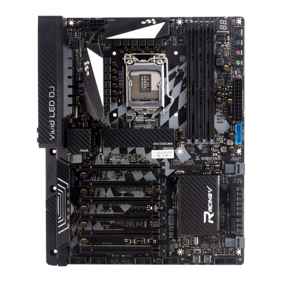
Page 6: Motherboard Layout
1.5 Motherboard Layout Note » represents the 1st pin. 6 | Chapter 1: Introduction... -
Page 7: Chapter 2: Hardware Installation
Z270GT9 & Z270GT8 Chapter 2: Hardware installation 2.1 Install Central Processing Unit (CPU) Step 1: Locate the CPU socket on the motherboard Note » Remove pin cap before installation, and make good preservation for future use. When the CPU is removed, cover the pin cap on the empty socket to ensure pin legs won’t be damaged. » The motherboard might equip with two different types of pin cap. Please refer below instruction to remove the pin cap. Step 2: Pull the socket locking lever out from the socket and then raise the lever up. - Page 8 Step 4: Hold processor with your thumb and index fingers, oriented as shown. Align the notches with the socket. Lower the processor straight down without tilting or sliding the processor in the socket. Step 5: Hold the CPU down firmly, and then lower the lever to locked position to complete the installation.
-
Page 9: Install A Heatsink
Z270GT9 & Z270GT8 2.2 Install a Heatsink Step 1: Place the CPU fan assembly on top of the installed CPU and make sure that the four fasteners match the motherboard holes. Orient the assembly and make the fan cable is closest to the CPU fan connector. -
Page 10: Connect Cooling Fans
2.3 Connect Cooling Fans These fan headers support cooling-fans built in the computer. The fan cable and connector may be different according to the fan manufacturer. CPU_FAN1/2: CPU Fan Header Pin Assignment Ground +12V FAN RPM rate sense Smart Fan Control (By Fan) SYS_FAN1/2/3: System Fan Header Pin Assignment Ground... - Page 11 Z270GT9 & Z270GT8 Step 1: Unlock a DIMM slot by pressing the retaining clips outward. Align a DIMM on the slot such that the notch on the DIMM matches the break on the slot. Step 2: Insert the DIMM vertically and firmly into the slot until the retaining clips snap back in place and the DIMM is properly seated.
-
Page 12: Expansion Slots
2.5 Expansion Slots PEX16_1: PCI-Express Gen3 x16 Slots (x16 speed) • PCI-Express 3.0 compliant. • Maximum theoretical realized bandwidth of 16GB/s simultaneously per direction, for an aggregate of 32GB/s totally. • When PEX16_2 is installed, PEX16_1 is x8 speed. PEX16_2: PCI-Express Gen3 x16 Slots (x8 speed) • ... - Page 13 Z270GT9 & Z270GT8 Install an Expansion Card You can install your expansion card by following steps: • Read the related expansion card’s instruction document before install the expansion card into the computer. • Remove your computer’s chassis cover, screws and slot bracket from the computer.
-
Page 14: Jumper & Switch Setting
2.6 Jumper & Switch Setting The illustration shows how to set up jumpers. When the jumper cap is placed on pins, the jumper is “close”, if not, that means the jumper is “open”. Pin opened Pin closed Pin 1-2 closed JCMOS1: Clear CMOS Jumper The jumper allows users to restore the BIOS safe setting and the CMOS data. -
Page 15: Headers & Connectors
Z270GT9 & Z270GT8 LN2_SW1: LN2 Mode Switch When the LN2 mode is ON, the CPU will run at its lowest frequency (e.g., 800MHz) to avoid unexpected system shutdown. OFF (Default) Note » We are not responsible for the damages or risks caused by overclocking. 2.7 Headers & Connectors MINI-SAS1/2: U.2 Connector • ... - Page 16 ATXPWR1: ATX Power Source Connector For better compatibility, we recommend to use a standard ATX 24-pin power supply for this connector. Make sure to find the correct orientation before plugging the connector. Assignment Assignment +3.3V +3.3V -12V +3.3V Ground Ground PS_ON Ground Ground...
- Page 17 Z270GT9 & Z270GT8 SATA3_1/3_2/3_3: Serial ATA Connectors These connectors connect to SATA hard disk drives via SATA cables. Assignment Ground Ground Ground Note » When PEX16_SB_2 slot is occupied, the SATA3_1, SATA3_2connector will be disabled. » When using SATA SSD module on PCIE-M2_1 slot, the SATA3_2L connector will be disabled. JFRONT_USB3_1: Header for USB 3.0 Ports at Front Panel This header allows user to add additional USB ports on the PC front panel, and also can be connected with a wide range of external peripherals.
- Page 18 F_USB1/2: Header for USB 2.0 Ports at Front Panel This header allows user to add additional USB ports on the PC front panel, and also can be connected with a wide range of external peripherals. Assignment +5V (fused) +5V (fused) USB- USB- USB+...
-
Page 19: Buttons, Indicators & Leds
Z270GT9 & Z270GT8 5050_RGBLED1/2: RGB LED Device (5050 SMD) Header This header providers 12V power and RGB control pins for RGB LED Device (5050 SMD). Assignment VCC12 LED_GREEN LED_RED LED_BLUE Note » Ensure proper pin connecting to your LED device, wrong connection may damage your LED device or motherboard. 2.8 Buttons, Indicators, LEDs Touch Buttons ECO Mode: Enabled ECO mode, it allows you save energy by slightly reducing system performance. - Page 20 Indicators BIOS POST Code Indicator: The indicator will show POST code while booting. Please refer to Chapter 4.3 for all the BIOS POST codes. LEDs Below LEDs are controlled by RACING GT program. Please refer to Chapter 3.3 for more detail software setting.
-
Page 21: Chapter 3: Uefi Bios & Software
The BIOS can be updated using either of the following utilities: • BIOSTAR BIOS Flasher: Using this utility, the BIOS can be updated from a file on a hard disk, a USB drive (a flash drive or a USB hard drive), or a CD-ROM. - Page 22 6. Select the proper BIOS file, and a message asking if you are sure to flash the BIOS file. Click “Yes” to start updating BIOS. 7. A dialog pops out after BIOS flash is completed, asking you to restart the system. Press the <Y> key to restart system.
- Page 23 Then, the BIOS Update is completed. BIOS Update Utility (through a BIOS file) 1. Installing BIOS Update Utility from the DVD Driver. 2. Download the proper BIOS from http://www.biostar.com.tw/ 3. Launch BIOS Update Utility and click the “Update BIOS” button on the main screen.
- Page 24 5. Choose the location for your BIOS file in the system. Please select the proper BIOS file, and then click on “Open”. It will take several minutes, please be patient. 6. After the BIOS Update process is finished, click on “OK” to reboot the system. 7.
-
Page 25: Software
Z270GT9 & Z270GT8 3.3 Software Installing Software Insert the Setup DVD to the optical drive. The driver installation program would appear if the Auto-run function has been enabled. Select Software Installation, and then click on the respective software title. Follow the on-screen instructions to complete the installation. - Page 26 eHot-Line eHot-Line is a convenient utility that helps you to contact with our Tech-Support system. This utility will collect the system information which is useful for analyzing the problem you may have encountered, and then send these information to our tech-support department to help you fix the problem.
- Page 27 Z270GT9 & Z270GT8 Enter the file name and then click “Save”. Your system information will be saved to a .txt file. Open the saved .txt file, you will see your system information including motherboard/BIOS/CPU/ video/device/OS information. This information is also concluded in the sent mail.
- Page 28 RACING GT RACING GT is an easy-to-use program that integrates several BIOSTAR utilities and allows users to configure these utilities simultaneously and seamlessly. System Information This System Information tab provides you an overview of the basic system information. 1. Clocks: Shows core speed, multiplier and bus speed.
- Page 29 Z270GT9 & Z270GT8 SmartEAR Smart EAR allows you to control system volume and adjust impedance setting (Low/High Gain) to optimize your headphone performance. You can easily enjoy high-quality and awesome sound. Requirements: 1. A chassis with front audio output jacks 2.
- Page 30 Vivid LED DJ Vivid LED DJ can adjust your color scheme of VIVID LED ARMOR , MOSFET Heatsink LED , RGB LED Device and Southbridge Heatsink LED. 1. Normal Mode: It balances energy consumption and system performance. 2. Default: All the setting are back to default. 3.
- Page 31 Z270GT9 & Z270GT8 H/W Monitor The HW Monitor tab allows you to monitor hardware voltage, fan speed, and temperature. 1. Temperature: Shows the current CPU and system temperature. 2. Fan: Shows the current fans’ speed. 3. Voltage: Shows the current voltages of CPU and memory.
- Page 32 OC/OV The OC/OV tab allows you to save or load the OC/OV setting profiles, change system frequency and voltage settings. 1. OC: Allows you to adjust overclocking profile values. 2. OV: Allows you to adjust voltage profile values. 3. Save: Store the profile values for future use. 4.
- Page 33 Z270GT9 & Z270GT8 LIGHTNING CHARGER (Quick Charge 2.0) Quick Charge 2.0 (QC 2.0) software function provides the user with quick charge and file transfer. LIGHTNING CHARGER UI: 1. TYPE: Allows users to select a Port. • All (Default): Enable Front USB3.0 Port1 & Front USB3.0 Port2 to transfer files or quick charge.
-
Page 34: Chapter 4: Useful Help
Chapter 4: Useful help 4.1 Driver Installation After you installed your operating system, please insert the Fully Setup Driver DVD into your optical drive and install the driver for better system performance. You will see the following window after you insert the DVD The setup guide will auto detect your motherboard and operating system. -
Page 35: Ami Bios Beep Code
Z270GT9 & Z270GT8 4.2 AMI BIOS Beep Code Boot Block Beep Codes Number of Beeps Description Continuing Memory sizing error or Memory module not found POST BIOS Beep Codes Number of Beeps Description Success booting. Display memory error (system video adapter) 4.3 AMI BIOS post code... - Page 36 Code Description South Bridge DXE initialization is started South Bridge DXE SMM initialization is started South Bridge devices initialization South Bridge DXE Initialization (South Bridge module specific) ACPI module initialization Boot Device Selection (BDS) phase is started Driver connecting is started PCI Bus initialization is started PCI Bus Hot Plug Controller Initialization PCI Bus Enumeration...
-
Page 37: Troubleshooting
Z270GT9 & Z270GT8 4.4 Troubleshooting Probable Solution 1. There is no power in the system. Power LED does 1. Make sure power cable is securely plugged in. not shine; the fan of the power supply does not work 2. Replace cable. -
Page 38: Raid Functions
4.5 RAID Functions RAID Definitions In a RAID 0 system data are split up in blocks that get written across all the drives in the array. By using multiple disks (at least 2) at the same time, this offers superior I/O performance. - Page 39 Z270GT9 & Z270GT8 RAID 10 combines the advantages (and disadvantages) of RAID 0 and RAID 1 in one single system. It provides security by mirroring all data on a secondary set of disks (disk 3 and 4 in the drawing below) while using striping across each set of disks to speed up data transfers.
-
Page 40: Intel® Optane™ Technology
4.6 Intel® Optane™ Technology (powered by 3D XPoint memory) With Intel® Optane™ technology you can unleash the power of your processor instead of it working at a fraction of its power. Eliminating that bottleneck requires better storage memory that is fast, inexpensive, and non-volatile. Intel® Optane technology has the potential to revolutionize big data, high-performance computing, virtualization, storage, cloud, gaming, and many other applications. -
Page 41: Appendix I: Specifications In Other Languages
& Intel® Rapid Storage Technology & RAID PCIe ﺗ����ﺪﻋﻢ : U.2 (32Gb/s) اﻟﻤﻮﺻﻞ Intel® Optane Technology & Intel i219V Intel X550AT(10GbE) - (Z270GT9) اﻟﺜﺎﻧﻴﺔ ، ﺗﺤﺪﻳﺪ ﺗﻠﻘﺎﺋﻲ ، اﻟﻨﺼﻒ ﻣﻴﺠﺎﺑﺎﻳﺖ 1000 ، اﻟﺜﺎﻧﻴﺔ ﻣﻴﺠﺎﺑﺎﻳﺖ 10000 5000 2500 1000 ﺷﺒﻜﺔ ﻣﺤﻠﻴﺔ... -
Page 42: German
* Windows 7 (32/64 Bit) / 8.1 (64 Bit) für die Intel® Core ™ Prozessorfamilie der 6. Generation * Biostar reserves the right to add or remove support for any OS with or without notice. 42 | APPENDIX I: Specifications in Other Languages... -
Page 43: Russian
* Windows 7 (32/64 бит) / 8,1 (64 бит) только для 6-го поколения Intel® Core ™ семейства Поддержка ОС процессоров * Biostar оставляет за собой право добавлять или удалять поддержку любой ОС, с уведомлением или без. Spanish APPENDIX I: Specifications in Other Languages | 43... -
Page 44: Thai
* Windows 7 (32/64 bits) / 8.1 (64 bits) sólo para la familia de procesadores Intel® Core ™ de 6ª Soporte OS generación * Biostar reserva su derecho de añadir o retirar el soporte para cada OS con o sin notificación. Thai 44 | APPENDIX I: Specifications in Other Languages... - Page 45 ครอบครั ว เท่ � นั ้ น * Biostar ขอสงวนสิ ท ธิ ์ ใ นก�รเพิ ่ ม หรื อ ถอดก�รสนั บ สนุ น สำ � หรั บ ระบบปฏิ บ ั ต ิ ก �ร OS ต่ � งๆ โดยไม่ ต ้ อ งแจ้ ง ให้ ท ร�บล่ ว งหน้ �...
-
Page 46: Appendix Ii: Quick Charger 2.0 Compatible Devices
APPENDIX II: Quick Charge 2.0 Compatible Devices Mobile Phone / Tablet Mobile Phone / Tablet Mobile Phone / Tablet Alcatel ldol 4 Nextbit Robin Sony Xperia Z5 Premium Alcatel ldol 4S Panasonic CM-1 Vertu Signature Touch Asus Transformer T100 Ramos Mos1 Vestel Venus V3 5070 Asus Zenfone 2 Samsung Galaxy A8 (KDDI Japan) - Page 47 FCC条款 依照FCC条款第15部分的规定,本装置已经通过测试并且符合Class B级数字装置的限制。 此条款限制了在安装过程中可能造成的有害射频干扰并提供了合理的防范措施。本装置在 使用时会产生无线射频辐射,如果没有依照本手册的指示安装和使用,可能会与无线通讯 装置产生干扰。然而,并不保证在特定的安装下不会发生任何干扰。 如果关闭和重新开启本设备后,仍确定本装置造成接收广播或电视的干扰,用户可以使用 以下列表中的一种或多种方法来减少干扰: • 重新安装或调整接收天线。 • 增加本设备与接收设备之间的距离。 • 连接设备连接到不同的插座以便于两个设备使用不同的回路。 • 咨询经销商或富有经验的无线电工程师, 以获得更多资讯 。 本用户手册内容的变更,恕不另行通知,制造商没有解释的义务。 本用户手册的所有内容若有任何错误,制造商没有义务为其承担任何责任。所有商标和产 品名称均有其各自所有权。 未经过书面许可,不得以任何形式(部分或全部)复制此手册信息。 免责说明 本手册内容系BIOSTAR 知识产权,版权归BIOSTAR 所有。我们本着对用户负责的态度, ® ® 精心地编写该手册,但不保证本手册的内容完全准确无误。BIOSTAR 有权在不知会用户 ® 的前提下对产品不断地进行改良、升级及对手册内容进行修正,实际状况请以产品实物为 准。本手册为纯技术文档,无任何暗示及影射第三方之内容,且不承担排版错误导致的用 户理解歧义。本手册中所涉及的第三方注册商标所有权归其制造商或品牌所有人。 CE符合性简短声明 我们声明此产品符合现行标准,并满足2004/108/CE, 2006/95/CE 和1999/05/CE指令规定的所有基本要求。 防静电操作规则 静电可能严重损坏您的设备,在处理主板以及其它的系统设备的时候要特别注意,避免和...
- Page 48 目录 第一章: 主板介绍 ������������������������������������������������������������������������������������������������������� 3 1.1 前言 ............................... 3 1.2 包装清单 ............................3 1.3 主板特性 ............................4 1.4 后置面板接口 ..........................5 1.5 主板布局图 ..........................6 第二章: 硬件安装 ������������������������������������������������������������������������������������������������������� 7 2.1 中央处理器(CPU) ........................7 2.2 散热片 ............................9 2.3 风扇接头 ............................. 10 2.4 系统内存...
-
Page 49: 第一章: 主板介绍
Z270GT9 & Z270GT8 第一章: 主板介绍 1�1 前言 感谢您选购我们的产品,在开始安装主板前,请仔细阅读以下安全指导说明: • 选择清洁稳定的工作环境。 • 操作前请确保计算机断开电源。 • 从抗静电袋取出主板之前 ,先轻触安全触地器或使用触地手腕带去除静电以确保安 全。 • 避免触摸主板上的零件。手持电路板的边缘 ,不要折曲或按压电路板。 • 安装之后 ,确认没有任何小零件置于机箱中,一些小的零件可能引起电流短路并可能 损坏设备。 • 确保计算机远离危险区域 ,如: 高温 、 潮湿、靠近水源的地方 。 • 计算机的工作温度应保持在0-45℃之间 • 为避免受伤,请注意以下幾點: 主板或連接器上尖銳的針腳 机箱上的粗糙边缘和尖角 破损的线缆可能引起短路 1�2 包装清单 • Serial ATA数据线 x4 •... -
Page 50: 主板特性
2个 U.2 (32Gb/s) : 支持 PCIe RAID 0,1,5 / Intel®快速储存技术& Intel® Optane技术 存储器 * 当PEX16_SB_2插槽被占用时,SATA3_1,SATA3_2接口将被禁用。 * 当PEX16_SB_1插槽被占用时,MINI-SAS1接口将被禁用。 * 当PEX16_SB_3插槽被占用时,MINI-SAS2接口将被禁用。 * 当安装SSD模块于 PCIE-M2_1 插槽时,SATA3_2 接口将会被禁用。 Intel X550AT (10GbE) - (Z270GT9) Intel i219V 网络 100/ 1000/ 2500/ 5000/ 10000 Mb/s自适应 10/ 100/ 1000 Mb/s 传输模式,半双工/全双工工作模式... -
Page 51: 后置面板接口
Z270GT9 & Z270GT8 1�4 后置面板接口 Z270GT9 Z270GT8 » 仅Intel集成显卡处理器支持HDMI、DP端口。 » 最高分辨率: HDMI: 4096 x 2160 @60Hz ,符合HDMI 2.0规范(支持高清数位内容保护2.2协定) HDMI 2: 4096 x 2160 @30Hz ,符合HDMI 1.4b规范 / DP: 4096 x 2304 @60Hz » HDMI 2.0仅支持uEFI模式 ,不支持BIOS / DOS视频输出。 » Line In / Side的扬声器配置选项:Line In仅限于5.1声道 / Side仅限于7.1声道。... -
Page 52: 主板布局图
1�5 主板布局图 » 标示为针脚1 6 | 第一章: 主板介绍... -
Page 53: 第二章: 硬件安装
Z270GT9 & Z270GT8 第二章: 硬件安装 2�1 中央处理器(CPU) 步骤1: 找到主板上的CPU插槽。 » 安装前请取掉针脚保护盖,并妥善保管以备后用。移开CPU后, 请盖上保护盖以确保针脚不被损 坏。 » 主板可能配有两种不同的针脚保护盖, 请参照以下指示取掉保护盖。 步骤2: 将拉杆从插槽移出并向上抬起 步骤3: 取掉针脚保护盖 第二章: 硬件安装 | 7... - Page 54 步骤4: 按照箭头的指示方向,将CPU上的切口对准插槽上相应的位置,然后将CPU放入 插槽处 步骤5: 固定CPU,将拉杆闭合。 » 请确保安装专为LGA1151插座設計的CPU。 » CPU必须按正确的方向放入 ,不要强行将CPU放进插槽以免损坏CPU。 8 | 第二章: 硬件安装...
-
Page 55: 散热片
Z270GT9 & Z270GT8 2�2 散热片 步骤1: 请将CPU风扇组件置于CPU顶部,确保四个钉钩对齐主板上的插孔,调整其方 位,使风扇电线与CPU风扇接口间距最近。确保钉钩插槽垂直指向散热片。 步骤2: 依次把对角2个钉钩同时向下按,以固定风扇,完成CPU安装。 » 如有必要,在安装散热风扇前请先涂抹散热膏于CPU表面。 » 请务必连接CPU风扇接口。 » 请参照CPU散热片的安装手册获取正确的安装信息。 第二章: 硬件安装 | 9... -
Page 56: 风扇接头
2�3 风扇接头 此风扇接头支持电脑内置的冷却风扇,风扇引线和插头可能因制造商而异。 CPU_FAN1/2: CPU 风扇接头 针 定义 接地 +12V FAN RPM rate sense Smart Fan Control (By Fan) SYS_FAN1/2/3: 系统风扇接头 针 定义 接地 +12V FAN RPM rate sense Smart Fan Control (By Fan) » CPU_FAN1/2 , SYS_FAN1/2/3支持4针脚和3针脚接口 ; 接线时请注意红线是正极需接到第二 个针脚,黑线接地需接到GND针脚。... - Page 57 Z270GT9 & Z270GT8 步骤1: 向外推开固定夹,打开DIMM插槽。将DIMM按顺序放在插槽上, DIMM上的切 口须与插槽凹口匹配。 步骤2: 垂直插入DIMM并固定好,直到固定夹跳回原位,DIMM就位。 » 如果DIMM未顺利插入 , 请勿强行按压。将DIMM拔出,再重插一次。 内存容量 DIMM插槽位置 模组 总内存 DIMMA1 4GB/8GB/16GB DIMMA2 4GB/8GB/16GB 最大为 64GB. DIMMB1 4GB/8GB/16GB DIMMB2 4GB/8GB/16GB 双通道内存安装 为激活主板双通道功能,使用内存模组必须符合以下要求: 成对安装相同密度的内存模 组。如下表所示 双通道状态 DIMMA1 DIMMA2 DIMMB1 DIMMB2 Enabled Enabled Enabled (“O”表示内存已安装,“X ”表示内存未安装。) »...
-
Page 58: 扩展槽
2�5 扩展槽 PEX16_1: PCI-Express Gen3 x16 插槽 (x16 模式) • 符合PCI-Express 3.0规范。 • 同步单向最大理论带宽为16GB/s, 总带宽为32GB/s。 • 当PEX16_2安装时 ,PEX16_1为x8速度 。 PEX16_2: PCI-Express Gen3 x16 插槽 (x8 模式) • 符合PCI-Express 3.0规范。 • 同步单向最大理论带宽为8GB/s, 总带宽为16GB/s。 • 安装PEX16_3时 ,PEX16_2为x4速度 。 PEX16_3 & PEX16_SB_1/2/3: PCI-Express Gen3 x16 插槽 (x4 模式) •... - Page 59 Z270GT9 & Z270GT8 安装扩展卡 请参照以下步骤安装扩展卡: • 安装扩展卡前请阅读扩展卡的相关指示说明。 • 打开电脑机箱后盖,移除螺丝和插槽支架。 • 将扩展卡按照正确的方向插入插槽, 直到扩展卡完全就位。 • 用螺丝将扩展卡的金属支架固定到机箱后置面板。 • 还原电脑机箱后盖。 • 开机 。如有必要, 可为扩展卡更改BIOS设置。 • 安装扩展卡的驱动。 安装M�2 COOLING 散热片 移除M.2 COOLING 散热片步骤: 步骤 1: 步骤 2: 步骤 3: 在M.2 COOLING散热片的 将M.2 SSD卡插入M.2插 安装M.2 SSD卡后,将M.2 边缘有两个螺丝,并在插入...
-
Page 60: 跳线设置
2�6 跳线设置 下图展示如何设置跳线。当跳帽放置在针脚上时,跳线为闭合(close)状态。否则跳线为 断开(open)状态。 打开 闭合 闭合 Pin 1-2 JCMOS1: 清空CMOS 跳线 用户可清空CMOS数据并恢复BIOS安全设置,请按照以下步骤操作以免损坏主板。 Pin 1-2 打开: 正常操作(默认) Pin 1-2 闭合: 清空CMOS数据 清空CMOS数据过程: 1. 断开AC电源。 2. 将跳线设置成1-2接脚闭合,建议可以使用一个金属物体如螺丝刀触碰1-2接脚。 3. 等待5秒钟。 4. 清空CMOS数据後,请确认跳线设置成1-2接脚打开。 5. 接通AC电源。 6. 开机然后按下<Del>键进入BIOS设置。 BIOS_SW1: 双BIOS切换开关 此开关让你从双BIOS (ROM1/ROM2) 中选择其一作为开机之用。 主BIOS (ROM1)运作中 LED指示燈(ROM1_LED1)將会点... -
Page 61: 接口和插槽
Z270GT9 & Z270GT8 LN2_SW1: LN2模式跳线 当启用LN2模式时,CPU将在其最低频率运行(例如,800MHz)以避免系统意外的当 机。 关闭OFF(默认) 启用ON » 我们不负责超频造成的损失或风险。 2�7 接口和插槽 MINI-SAS1/2: U�2接口 • 主板配备了一个U.2连接器,并支持PCIe 3.0 x4的NVMe快速存储设备。 • 支持 Intel®快速储存技术 & Intel® Optane技术 。 » 当PEX16_SB_1插槽被占用时 ,MINI-SAS1接口将被禁用。 » 当PEX16_SB_3插槽被占用时 ,MINI-SAS2接口将被禁用。 第二章: 硬件安装 | 15... - Page 62 ATXPWR1: ATX电源接口 为了更好的兼容性,我们建议使用标准的ATX24-pin电源供应此接口的电源。 针 定义 针 定义 +3.3V +3.3V -12V +3.3V 接地 接地 PS_ON 接地 接地 接地 接地 接地 PW_OK 唤醒电压+5V +12V +12V 接地 +3.3V ATXPWR2: ATX电源接口 此接口给CPU电路提供+12V电压。若CPU电源插头为4针脚,请将其插入ATXPWR2的 1-2-5-6针脚。 针 定义 +12V +12V +12V +12V 接地 接地 接地 接地 » 开机前, 请确保ATXPWR1和ATXPWR2接口都已插上电源。 »...
- Page 63 Z270GT9 & Z270GT8 SATA3_1/3_2/3_3: 串行ATA接口 此接口通过SATA数据线连接SATA硬盘。 针 定义 接地 接地 接地 » 当PEX16_SB_2插槽被占用时 , SATA3_1 , SATA3_2接口将被禁用。 » 当安装SSD模块于 PCIE-M2_1 插槽时 , SATA3_2 接口将会被禁用。 JFRONT_USB3_1: 前置面板USB 3�0接头 PC前置面板支持附加的USB数据线,也可连接即插即用外围设备。 • 支持闪电充电器,电压 / 电流为12V / 1.5A输出並支持苹果模式(5V / 2.4A) 。 针 定义 针...
- Page 64 F_USB1/2: 前置面板USB 2�0接头 PC前置面板支持附加的USB数据线,也可连接即插即用外围设备。 针 定义 +5V (fused) +5V (fused) USB- USB- USB+ USB+ 接地 接地 TB1: Thunderbolt 3接头 PC前置面板支持附加的Thunderbolt端口,也可连接即插即用外围设备。 针 定义 Force Power CIO Plug Event I2C_MASTER_DATA SLP_3# I2C_MATSTER_CLK SLP_S5_S4# PA_PPS_INT# 接地 接地 F_AUDIO1: 前置面板音频接头 此接头可连接音频输出数据线,支持HD(高清)音频和AC’97。 HD Audio AC’97 针...
-
Page 65: 智能开关/指示器/Led 灯
Z270GT9 & Z270GT8 5050_RGBLED1/2: RGB LED装置 (5050 SMD) 接头 此接头提供12V电源与RGB控制讯号,可连接RGB LED装置(5050 SMD)。 针 定义 VCC12 LED_GREEN LED_RED LED_BLUE » 确保正确將针脚连接到LED装置 ,错误的连接可能会损坏您的LED装置或主板。 2�8 智能开关/指示器/LED 灯 触控按钮 ECO模式: 启动ECO模式,会在可能情况下稍微地降低系统性能,以节省能源。 SPORT模式: 启动SPORT模式,会以最大限度提高系统性能,但可能使用较多的能源。 Reset: 轻触此按钮以重启系统。 Power: 轻触此按钮以开启或关闭系统。 » ECO/SPORT 模式按钮仅限于Windows环境下运行RACING GT软件时才可以使用。 第二章: 硬件安装 | 19... - Page 66 指示器 BIOS开机自检代码指示器: 当系统启动时此指示器会显示开机自检代 码。若要获取更多详情,请参考4.3章节的 BIOS开机自检代码。 LED灯 下面的LED灯由RACING GT软件控制。请参考3.3章节的软件设置。 1. RGB LED 接头 2. MOSFET散热片LED灯 3. VIVID 盔甲LED灯 4. 南侨散热片LED灯 20 | 第二章: 硬件安装...
-
Page 67: 第三章: Uefi Bios和软件
3�1 UEFI BIOS设置 • BIOS设置程序可用于查看和更改计算机的BIOS设置。开机自检时 ,按<DEL>键可进入 BIOS设置程序。 • 更多相关UEFI BIOS设置信息 , 请参考网站上的UEFI BIOS手册。 3�2 刷新BIOS 以下任意一种工具都可以刷新BIOS: • BIOSTAR BIOS Flasher: 使用此工具 ,BIOS可通过硬盘上的文件刷新 ,USB驱动刷新 , 或者CD-ROM 刷新。 • BIOSTAR BIOS刷新工具: 能够在Windows 环境下自动刷新。使用此工具,BIOS可通 过硬盘上的文件刷新 , USB驱动刷新 ,CD-ROM 刷新或者从网站上的文件地址刷新。 BIOSTAR BIOS Flasher » 此工具仅允许可使用FAT32/16格式化或单个分区的存储设备。... - Page 68 7. BIOS刷新后会弹出是否重启系统的对话框。 按<Y>重启系统 8. 系统引导并出现相关标识信息时,按<DEL>键进入BIOS设置。 选择<Save & Exit>,使用<Restore Defaults>功能加载系统默认值,然后选择<Save Changes and Reset>来重启系统,完成BIOS刷新。 BIOS刷新工具(通过网络) 1. 用DVD驱动安装BIOS Update Utility。 2. 使用此功能时,请确保电脑联网。 3. 打开BIOS刷新工具,然后点击”Online Update”按钮。 4. 屏幕弹出是否执行刷新BIOS程序的对话请 求,点击”Yes”开始刷新BIOS。 5. 如果BIOS有新版本,屏幕会弹出提示您下 载最新版本的对话框。点击”Yes”下载。 6. 完成下载后,屏幕弹出提示您刷新 BIOS的对话框,点击”Yes”开始刷新。 22 | 第三章: UEFI BIOS和软件...
- Page 69 Z270GT9 & Z270GT8 7. 刷新程序结束后,屏幕弹出提示您重启系 统的对话框。点击”OK”重启系统。 8. 系统引导并出现相关标识信息时,按<DEL>键进入BIOS设置。 选择<Save & Exit>,使用<Restore Defaults>功能加载系统默认值,然后选择<Save Changes and Reset>来重启系统,完成BIOS刷新。 BIOS刷新工具(通过BIOS文件) 1. 用DVD驱动安装BIOS刷新工具。 2. 从我们的网站www.biostar.com.tw 下载合适的BIOS. 3. 在主页面打开BIOS Updat Utility,然后点 击”Update BIOS”按钮。 4. 屏幕弹出是否执行刷新BIOS程序的对话请 求,点击”OK”开始刷新BIOS。 5. 选择BIOS文件的存放目录。然后选择合适的 BIOS文件,点击”Open”。 刷新BIOS要花几分钟时间,请耐心等待。 6. BIOS刷新过程结束后,点击”OK”重启系 统。 第三章: UEFI BIOS和软件 | 23...
- Page 70 7. 系统引导并出现相关标识信息时,按<DEL>键进入BIOS设置。 选择<Save & Exit>,使用<Restore Defaults>功能加载系统默认值,然后选择<Save Changes and Reset>来重启系统,完成BIOS刷新。 BIOS备份 点击BIOS备份按钮,选择存储备份文件的合适 目录,然后点击”Save”。 24 | 第三章: UEFI BIOS和软件...
- Page 71 Z270GT9 & Z270GT8 3�3 软件 安装软件 1. 将光盘放入光驱,若Autorun功能已激活,驱动安装程序将会出现。 2. 选择Software Installation,然后点击各软件图标。 3. 根据屏幕上的指令完成安装。 启动软件 安装程序完成后,桌面上将出现软件图标。请双击图标启动软件工具。 » 所有软件的相关信息和内容若有变更 ,恕不另行通知。为使系统性能更佳,软件会不断升级。 » 下面的图片和信息仅供参考, 此主板的实际信息和设置可能与手册稍有差异。 BIOScreen 工具 此实用工具可以将开机画面个性化。您可以选择BMP格式来自定义计算机开机画面。 请参照以下步骤来更新开机画面: • 加载画面(Load Image):选择图片作为开机画面。 • 转换(Transform):转换图片并预览 。 • 更新BIOS(Update Bios): 将图片写入BIOS内存,然后完成更新。 第三章: UEFI BIOS和软件 | 25...
- Page 72 eHot-Line eHot-Line是有助于您联系技术支持系统的便捷工具。此工具将收集系统信息,当您遇 到问题时,可提供有利分析,并发送这些信息至我们的技术支持部门,从而帮助解决此 问题。 填好表格信息后,点击“Send”发送邮件。将 出现一个确认信息对话框;点击“Send”确认 发送点击“Do Not Send”则取消操作。 如您想保存此信息到文本文件里,点击“Save As…”,出现一个保存对话框,输入文件名即 可。 26 | 第三章: UEFI BIOS和软件...
- Page 73 Z270GT9 & Z270GT8 输入文件名,点击“Save”,系统信息将被保 存至文本文件里。 打开已保存的文本文件,显示相关系统信息(包 括主板/BIOS/CPU/视频设备/OS)。这些信息 当然也在已发送的邮件里。 » 在使用此工具前, 请将Outlook Express设置为您的默认电子邮件连接程序。 » 我们将为用户资料保密,所以使用eHot-Line服务时 , 请放心提供您的系统信息。 » 若您未将Outlook Express设置为默认电子邮件连接程序, 也可保存您的系统信息到文件里,然 后用其它电子邮件工具发送此文件到我们的技术支持。 请访问网站http://www.biostar.com.tw/app/en/about/contact.php获取我们的联系信息。 第三章: UEFI BIOS和软件 | 27...
- Page 74 RACING GT Utility RACING GT軟件集成几个映泰的实用程序並十分易于使用,允许用户同时无缝地配置这 些实用程序。 系统信息 提供您的基本系统信息的概述。 1� 时钟频率:显示核心频率,倍频和总线速度。 2� 主板:显示主板信息。 3� 处理器:显示处理器信息。 4� 内存:显示内存信息。 28 | 第三章: UEFI BIOS和软件...
- Page 75 Z270GT9 & Z270GT8 耳放调控 耳放调控允许您控制系统音量,调整阻抗设置(低/高增益),以优化您的耳机性能。 讓您可以轻松享受高品质的声音。 设置需求: 1. 带有前置音频输出插孔的机箱。 2. 耳机或头戴式耳机。 3. Windows 7 (32/64bit) / 8.1(64bit) /10(64bit)操作系统。 安装指南: 1. 确保机箱前置音频线正确连接至主板上的前置音频接头。 2. 从驱动DVD上安装RACING GT软件。 3. 将耳机或头戴式耳机连接至机箱前置或后部的音频输出接口,並启用RACING软 件。 » 如果您想使用AC’ 97前置音频输出线, 请禁用 “前置面板插孔检测功能” 。此功能在系统音频工 具中可见。 1� 音量:可调节音量大小。 2� 静音:可切换到静音状态。 3� 增益开关:使用低阻抗耳机时调至低(LO),使用高阻抗耳机时调至高(HI)。...
- Page 76 炫彩LED 炫彩LED可调整VIVID 盔甲LED灯、MOSFET散热片LED灯、RGB LED装置以及南侨散 热片LED灯的配色方案。 1� 普通模式(Normal):自动平衡系统性能与电源消耗。 2� 默认设置:所有设置都恢复为默认。 3� 节能模式(ECO):稍微地降低系统性能以节省能源。 4� 高性能模式(Sport):以最大限度地提高系统性能。 » ECO及Sport板载按钮以及LED灯仅限于Windows环境下运行RACING GT软件时才可以使用。 » Normal 、 ECO和Sport模式的配色方案可以通过下面的设置项目进行调整。 5� LED分区调控:选择LED开启区块。 • 烈火战车 : 所有区块的LED灯全亮。 • 系统 : 显示system区块(MOSFET散热片LED灯、南侨散热片LED灯、VIVID 盔甲 LED灯)的LED灯。 • LED接头1 : 显示LED接头 1 区块(RGB LED装置)的LED灯。 • LED接头2 : 显示LED接头 2 区块(RGB LED装置)的LED灯。 »...
- Page 77 Z270GT9 & Z270GT8 硬件监测 允许您监控硬件电压,风扇转速和温度。 1� 温度信息:显示当前CPU和系统温度。 2� 风扇转速:显示当前风扇速度。 3� 电压信息:显示CPU和内存的当前电压。 4� CPU风扇/系统风扇:选择你的设置风扇。 5� 校准:校准风扇转速。 6� 关闭:关闭智能风扇功能。 7� 自动:启用智能风扇功能。 第三章: UEFI BIOS和软件 | 31...
- Page 78 超频设置 允许您保存或加载超频的设定参数值,以及更改系统的频率与电压设置。 1� 超频调节:您可以调节超频参数值。 2� 电压调节:您可以调节电压参数值。 3� 保存:存储参数值以供将来使用。 4� 载入:从文件载入参数值。 5� 应用:应用当前的参数值。 » 并非所有类型的CPU性能都能超出理想的超频设置 ,因CPU类型而异。 » 超频是一个可选程序,而并非必须的; 不建议无经验用户使用。因此,由于超频导致的任何硬件 损坏我们不予负责。 对超频性能我们也不做任何担保。 32 | 第三章: UEFI BIOS和软件...
- Page 79 Z270GT9 & Z270GT8 LIGHTNING CHARGER (Quick Charge 2�0) Quick Charge 2.0 (QC 2.0)软件功能为用户提供快速充电和文件传输。 LIGHTNING CHARGER 使用者界面: 1� TYPE: 供选择全部或单一端口,并为选择的端口做使用设定。 • 全部(预设值) :同时设定前置面板USB 3.0接头端口1和前置面板USB 3.0接头端口2 并选择充电或资料传输模式 。 • Port 1 / 2 - 设定前置面板USB 3.0接头端口1 /2 ,并选择充电或资料传输模式 。 » 所有的端口设定均无法同时选择充电及资料传输功能。 » 如重新选择端口后,则设定模式将持续保留先前的设置。...
-
Page 80: 第四章:帮助信息
第四章:帮助信息 4�1 驱动程序安装注意事项 为获得更好的系统性能,在操作系统安装完成后,请插入您的系统驱动到光驱并安装。 插入DVD后,将出现如下所示窗口。 此设置向导将自动检测您的主板和操作系统。 A� 驱动程序安装 安装驱动程序,请点击驱动器图标。设置向导将列出主板兼容驱动和操作系统。点击各 设备驱动程序,以开始安装进程。 B� 软件安装 安装软件,请点击软件图标。设置向导将列出系统可用软件,点击各软件名称,以开始 安装进程。 C� 使用手册 除了书本形式的手册,我们也提供光盘形式的使用指南。点击Manual图标,浏览可用 相关使用指南。 » 在插入驱动之后,如此窗口未出现, 请用文件浏览器查找并执行SETUP.EXE文件。 » 若需要Acrobat Reader打开manual文件。请从网站http://get.adobe.com/reader/下载最新 版本的Acrobat Reader软件。 34 | 第四章:帮助信息... -
Page 81: Ami Bios 哔声代码
Z270GT9 & Z270GT8 4�2 AMI BIOS 哔声代码 引导模块哔声代码 哔声次数 含义 持续哔声 持续哔声 BIOS 开机自检哔声代码 哔声次数 含义 系统引导成功 显存错误(系统视频适配器) 4�3 AMI BIOS 开机自检代码 代码 含义 PEI核心启动 CPU Pre-memory初始化启动 北桥Pre-memory初始化启动 南桥Pre-memory初始化启动 内存初始化,读取SPD数据 内存初始化,检测Memory presence 2D 内存初始化,编程内存时序信息 内存初始化,配置内存 内存初始化(其他) 内存安装完成 CPU post-memory初始化启动 CPU post-memory初始化,Cache初始化... - Page 82 代码 含义 南桥DXE初始化启动 南桥DXE SMM初始化启动 南桥设备初始化 南桥DXE初始化 ACPI模组初始化 引导设备选择阶段启动 驱动连接启动 PCI总线初始化启动 PCI总线热拔插控制器初始化 PCI总线列举 PCI总线请求资源 PCI总线分配资源 控制台输出设备连接 控制台输入设备连接 高级IO初始化 USB初始化启动 USB复位 USB检测 9D USB启用 IDE初始化启动 IDE复位 IDE检测 IDE启用 SCSI初始化启动 SCSI复位 SCSI检测 SCSI启用 设置校对密码 设置开始 设置输入等待 AD 准备启动环境 传统启动环境 退出启动环境 虚拟地址图开始 虚拟地址图结束 传统可选ROM初始化...
-
Page 83: 问题解答
Z270GT9 & Z270GT8 4�4 问题解答 问题 解决方法 1. 系统没有电,电源指示灯不亮,电源风 1. 确定电源线是否接好。 扇不转动。 2. 更换线材。 2. 键盘上的指示灯不亮。 3. 联系技术支持。 系统不起作用。键盘指示灯亮,电源指示 用力按压内存两端,确保内存安置于插槽 灯亮,硬盘正常运作。 中。 1. 检查硬盘与主板的连线,确定各连线是 否确实接好,检查标准CMOS设置中的驱 系统不能从硬盘启动,能从光盘启动。 动类型。 2. 硬盘随时都有可能坏掉,所以备份硬盘 数据是很重要的。 1. 备份数据和应用程序。 系统只能从光盘启动。硬盘能被读,应用 2. 重新格式化硬盘。用后备盘重新安装应 程序能被使用,但是不能从硬盘启动。 用程序和数据。 屏幕提示“Invalid Configuration” 或... -
Page 84: Raid 功能
4�5 RAID 功能 RAID 定义 创建带区集,在同一时间内向多块磁盘写入数据,通过 把数据分成多个数据块(Block)并行写入/读出多个磁 盘以提高访问磁盘的速度分散到所有的硬盘中同时进 行读写,在整个磁盘阵列建立过程中,以系统环境为基 础,指数的大小决定了每块磁盘的容量。此技术可减少 整个磁盘的存取时间和提供高速带宽。 性能及优点 • 驱动器: 最少2块硬盘 , 最多达6块或8块, 取决于平台。 • Uses: 使用RAID 0来提高磁盘的性能和吞吐量 ,但没有冗余或错误修复能力。 • 优点: 增加磁盘的容量。 • 缺点: 整个系统是非常不可靠的,如果出现故障, 无法进行任何补救.整个数据都会丢 失。 • 容错: 否。 每次读写实际上是在磁盘阵列系统中(RAID 1),通过2个 磁盘驱动器并行完成的。RAID 1或镜像模式能够自动对 数据进行备份,通过将一块硬盘中的数据完整复制到另 外一块硬盘实现数据的冗余。假如由于硬盘的损坏,导 致驱动失败,或是容量过大,RAID1可以提供一个数据... - Page 85 Z270GT9 & Z270GT8 RAID 10模式是对RAID 0/ RAID 1两种不同 模式的结合,可以同时支持带区集和镜像, 这样既可以提升速度又可以加强数据的安全 性。 性能及优点 • 驱动器: 最少4块硬盘 , 最多6或8块。 • 优点: 容量和性能的优化允许冗余的自动化。在一个阵列, 可以同时使用其它的RAID, 并允许剩余的磁盘。 • 缺点: 数据冗余需要两倍可用磁盘空间,与RAID1相同。 • 容错: 是。 RAID 5数据块和奇偶块信息跨3块或更多块 驱动器。奇偶校验数据分散分布在磁盘阵列 的全部硬盘。容错的维护是由确保数据块传 输奇偶块信息实现的,此信息被放置在不同 于那些自身可以储存信息的驱动盘里。 性能及优点 • 驱动器: 最少3块硬盘。 • 使用: RAID 5被推荐用于处理交易和普通操作服务。...
-
Page 86: 英特尔® Optane™ 技术
4�6 英特尔 Optane 技术 (由3D XPoint内存供电) ® 透过英特尔® Optane™技术,您可以完全释放处理器的威力,而不只是运用一小部分 而已。要突破这个瓶颈,则需要更佳的储存记忆体,具备快速、价格实惠、非挥发性的 特色。 英特尔® Optane 技术具有为大数据、高效能运算、虚拟化、储存、云端、游戏 与其他多种应用带来革命性改变的潜力。 性能及优点 : • 大容量内存数据库 • 快速系统恢复 • 低延迟 • 高耐力 英特尔 Optane 技术的需求简介: ® • 英特尔® Optane 内存或存储。 • 英特尔® 第7代核心中央处理器。 • 在支持英特尔®Optane 技术的端口中安装英特尔®Optane 内存或存储器。 (详情 请参考第4页)... -
Page 87: 附录I:产品中有毒有害物质或元素的名称及含量
Z270GT9 & Z270GT8 附录I:产品中有毒有害物质或元素的名称及含量 有毒有害物质或元素 部件名称 六价铬 多溴联苯 多溴二苯醚 铅 (Pb) 汞 (Hg) 镉 (Cd) (Cr(VI)) (PBB) (PBDE) PCB板 结构件 芯片及其它 主动零件 连接器 被动电子元 器件 焊接金属 线材 助焊剂,散 热 膏,标签 及其它耗材 O:表示该有毒有害物质在该部件所有均质材料中的含量在SJ/T11363-2006标准规定的限量要求以下。 X:表示该有毒有害物质至少在该部件的某一均质材料中的含量超出SJ/T11363-2006标准规定的限量要求。 备注:在芯片及其它主动零件、连接器、被动电子元器件Pb栏位中有打X,表示Pb在该部件的某一均质材料中的含量超出 SJ/T11363-2006标准规定的限量要求,但均符合欧盟ROHS指令豁免条款。 附录I:产品中有毒有害物质或元素的名称及含量 | 41... -
Page 88: 附录Ii:quick Charge 2�0(快速充电2�0)兼容设备列表
附录II:Quick Charge 2�0(快速充电2�0)兼容设备列表 手机 / 平板 手机 / 平板 手机 / 平板 Alcatel ldol 4 Nextbit Robin Sony Xperia Z5 Premium Alcatel ldol 4S Panasonic CM-1 Vertu Signature Touch Asus Transformer T100 Ramos Mos1 Vestel Venus V3 5070 Asus Zenfone 2 Samsung Galaxy A8 (KDDI Japan) Vestel Venus V3 5570 BlackBerry Priv...
Need help?
Do you have a question about the Z270GT9 and is the answer not in the manual?
Questions and answers