Table of Contents
Advertisement
Quick Links
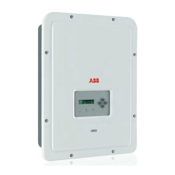
ABB solar inverters
Quick installation guide
UNO-2.0/3.0/3.6/4.2-TL-OUTD
(from 2.0 to 4.2 kW)
EN
In addition to the notes below, please read and follow the safety and installation information
provided in the installation manual. The technical documentation and the interface and
management software for the product are available on the website.
This equipment must be used following the guidelines provided in the manual.
Failure to do so may impair the inverter safety features.
3.
Transportation and handling
Transport of the equipment, especially by road, must be carried out using suitable ways and means in order
to protect the components from violent shocks, humidity, vibration, etc.
Lifting
The means used for lifting must be suitable to bear the weight of the equipment.
Unpacking and checking
The components of the packaging must be removed and disposed of in accordance with the regulations in
force in the country of installation.
When you open the package, check that the equipment is undamaged and make sure all the components
are present.
If any defects or damages are detected, please stop operating, contact the carrier and also promptly inform
the ABB Service Department.
Weight of the modules of the equipment
Model
Weight
UNO-2.0/3.0-TL-OUTD
UNO-2.0/3.0-TL-OUTD-S
12 Kg
UNO-3.6/4.2-TL-OUTD
UNO-3.6/4.2-TL-OUTD-S
4.
Environmental checks
- Consult the technical data to check the environmental conditions to be observed
- Installation of the unit in a location exposed to direct sunlight must be avoided (otherwise the warranty
will be cancelled) as it may cause:
1. power limitation phenomena in the inverter (with a resulting decreased energy production by the
system)
2. premature wear of the electrical/electromechanical components
3. premature wear of the mechanical components (gaskets) and of the user interface (display)
- Do not install in small closed rooms where air cannot circulate freely
- Always ensure that the flow of air around the inverter is not blocked so as to prevent overheating.
- Do not install in places where gases or flammable substances may be present
- Do not install in rooms where people live or where the prolonged presence of people or animals is ex-
pected, because of the noise level that the inverter produces during operation. The level of the sound
emission is heavily influenced by where the inverter is installed (for example: the type of surface
around the inverter, the general properties of the room, etc.) and the quality of the electricity supply.
Installations above 2000 metres
On account of the rarefaction of the air (at high altitudes), particular conditions may occur:
- Less efficient cooling and therefore a greater likelihood of the device going into derating because of
high internal temperatures
- Reduction in the dielectric resistance of the air that, in the presence of high operating voltages (DC
input), can cause arcing (electrical discharges) that may reach the point of damaging the inverter
All installations at altitudes of over 2000 metres must be assessed case by case with the ABB
Service department.
Installation site
- Install on a wall or strong structure capable of bearing the weight of the equipment
- Install in safe, easy to reach places.
- If possible, install at eye-level so that the display can be seen easily
- Install at a height that takes account of the weight of the equipment
- Install vertically with a maximum inclination of 5° (forward or backward)
- Choose a place that enables sufficient space to be left around the unit to enable
easy installation and removal of the object from the assembly surface; respect the
minimum distances indicated
- In the case of multiple installation position the inverters alongside each other;
if the space available does not allow this arrangement, position the inverters in
a staggered arrangement as shown in the figure so that heat dissipation is not
affected by other inverters
15
cm
Final installation of the inverter must not compromise access to any discon-
nection devices that may be located externally.
Please refer to the warranty terms and conditions available on the website
and evaluate any possible exclusions due to improper installation.
10cm
10cm
20
cm
1.
© Copyright 2014 Power-One Italy Spa. All rights reserved. Reproduction, use or disclosure to third parties without express written authority is strictly forbidden.
© Copyright 2014 Power-One Italy Spa. All rights reserved. Reproduction, use or disclosure to third parties without express written authority is strictly forbidden.
The labels on the inverter carry the branding, the main technical data and the identification of the equipment and the manufacturer
DIN V VDE V 0126-1-1
PROTECTIVE CLASS: I
Made in Italy
www.abb.com/solar
MODEL:
www.abb.com/solar
SOLAR
INVERTER
UNO-2.0-TL-OUTD
SOLAR
V
600 V
V
230 V 1Ø
V
dc max
acr
dc max
V
dc MPP
80 - 580 V
f
r
50 Hz
V
dc MPP
V
180 - 500 V
S
2000 VA
V
dc, Full Power
max
dc, Full Power
I
12.5 A
P
acr (cos = 1)
2000 W @ 45 °C amb.
I
dc max
φ
dc max
I
16 A
P
1800 W @ 45 °C amb.
I
sc max
acr (cos = ± 0.9)
φ
sc max
I
10 A
ac max
IP65
-25 to + 60 °C
5 minutes
-25 to + 60 °C
-13 to +140 °F
-13 to +140 °F
DIN V VDE V 0126-1-1
PROTECTIVE CLASS: I
Made in Italy
www.abb.com/solar
www.abb.com/solar
MODEL:
SOLAR
INVERTER
UNO-3.6-TL-OUTD
SOLAR
850 V
230 V 1Ø
V
dc max
V
acr
V
dc max
V
350 - 820 V
f
50 Hz
V
dc MPP
r
dc MPP
380 - 700 V
V
dc, Full Power
S
max
3600 VA
V
dc, Full Power
I
11 A
P
3600 W @ 45 °C amb.
I
dc max
acr (cos = 1)
φ
dc max
I
sc max
15 A
P
acr (cos = ± 0.9)
3240 W @ 45 °C amb.
I
sc max
φ
I
16 A
ac max
IP65
-25 to + 60 °C
-25 to + 60 °C
5 minutes
-13 to +140 °F
-13 to +140 °F
The labels on the equipment must absolutely NOT be removed, damaged, dirtied, hidden, etc.
LABEL MATERIAL: 3M type 7331 (UL R/C, PGJI2)
LABEL MATERIAL: 3M type 7331 (UL R/C, PGJI2)
INKS:
If the service password is requested, the field to be used is the serial number -SN: YYWWSSSSSS
Refer to UL File MH16411
INKS:
LABEL CONTENT:
Fixed as shown in the picture
LABEL CONTENT:
In the manual and/or in some cases on the equipment, the danger or hazard zones are indicated with signs, labels, symbols or icons.
SIZE:
63 mm (height) x 90 mm (width)
SIZE:
Obligation to consult
Pantone
Pantone
manual
Process Cyan C
Process Yellow C
Process Cyan C
Protection rating of
IP65
All
used
material
and finished product, must meet the requirements of the current RoHS
All
used
material
D
i
recti
and finished product, must meet the requirements of the current RoHS
ve 2002/95/EC.
Modified
Title
Title
equipment
29/05/2015
Issued
Regulatory Label of UNO-2.0-TL-OUTD
D
esign approved
Regulatory Label of UNO-3.0-TL-OUTD
29/05/2015
LABEL MATERIAL: 3M type 7331 (UL R/C, PGJI2)
LABEL MATERIAL: 3M type 7331 (UL R/C, PGJI2)
29/05/2015
UNO LOW COST (V1N)
Elec. Eng. approved
UNO LOW COST (V1N)
INKS:
Refer to UL File MH16411
Mfg. approved
INKS:
29/05/2015
Positive pole and negative
LABEL CONTENT:
Size
Scale
Fixed as shown in the picture
Dim. in mm
Sheet
Drawing No.
LABEL CONTENT:
A4
1:1
63 mm (height) x 90 mm (width)
1/1
XLP .V1N02.0AL
SIZE:
pole of the input voltage
SIZE:
(DC)
Pantone
Pantone
Process Cyan C
Process Yellow C
Process Cyan C
2.
All
used
material
and finished product, must meet the requirements of the current RoHS
All
used
material
D
i
recti
and finished product, must meet the requirements of the current RoHS
ve 2002/95/EC.
Title
Title
Modified
The inverter models to which this installation guide refers are available in four power ratings: 2.0 kW, 3.0 kW, 3.6 kW and 4.2 kW.
Issued
29/05/2015
Regulatory Label of UNO-3.6-TL-OUTD
D
esign approved
Regulatory Label of UNO-4.2-TL-OUTD
29/05/2015
Two types are available for each model: standard or with DC disconnect switch (Version -S).
29/05/2015
UNO LOW COST (V1N)
Elec. Eng. approved
UNO LOW COST (V1N)
Mfg. approved
29/05/2015
Size
Scale
Dim. in mm
Sheet
Drawing No.
A4
1:1
1/1
XLP .V1N06.0AL
Main components
01
Bracket
02
Locking screws
03
Heat sink
04
Anti-condensation valve
05
Front cover
06
LED panel
07
Display
08
Keyboard
09
DC input connectors
10
AC output connector
12
SD Card slot
14
RS485 connector
16
DC disconnect switch
18
Stand-alone board (optional)
19
External ground connection
20
Service cable glands
5.
Available components
Bracket for wall mounting
Plug, screw and washer for wall
mounting
M5x10 screw and M5 washer to lock
bracket
M5x10 screw and M5 contact washer
for external ground connection
Two-hole gasket for M20 signal cable
gland and TGM58 cover
6.
Wall mounting
During installation do not place the inverter with the front cover
01
- Position the bracket
so that it is perfectly level on the wall and use it as a template for
drilling.
- Make the 2 holes necessary, using a drill with a 10 mm. diameter bit. The depth of the holes
must be around 70 mm.
- Secure the bracket to the wall with the two 10 mm wall plugs supplied with it.
- Attach the inverter by inserting the two tabs on the bracket
(figures A1 and A2).
- Secure the inverter to the bracket by screwing the lock screws
inverter (figure A3).
- If necessary unscrew the 8 screws and open the front cover
connections.
Do not open the inverter in the case of rain, snow or a high level of humidity
(>95%)
• Once the connections have been made proceed to closing the cover by tightening the 8
screws on the front, adhering to the tightening sequence and torque (2.5Nm).
7.
Check for correct polarity in the input strings and absence of any leakage to ground in the PV generator.
When exposed to sunlight, the PV panels supply DC direct voltage to the inverter.
The inside of the inverter may only be accessed after the equipment has been disconnected from the grid and from the photovoltaic
generator.
Warning! The inverters referred to in this document are TRANSFORMERLESS. This typology implies the use of insulated photovoltaic
panels (IEC61730 Class A Rating) and the need to keep the photovoltaic generator floating with respect to the ground: no terminal of the
generator must be grounded.
The inverter has a single input channel (MPPT) and is equipped with a pair of quick fit connectors
connect the PV generator
If the input strings should be connectd in parallel, they must have the same installation conditions
(number of panels in series, type of panels, orientation and inclination).
Comply with the maximum input current relating to the quick fit connectors.
- Refer to the document "String inverter – Product Manual appendix" available at www.abb.com/solarinver-
ters to know the brand and the model of the quick fit connector. Depending on the model of the connector
of the own inverter, it is necessary to use the same model and the respective counterpart (check the
compliant counterpart on the website of the manufacturer or in ABB).
Using corresponding parts that are not compliant with the quick fit connector models on the
inverter could cause serious damage to the unit and lead to invalidation of the warranty.
- Connect the DC input and always check the tightness of the connectors
DIN V VDE V 0126-1-1
PROTECTIVE CLASS: I
Made in Italy
MODEL:
INVERTER
UNO-3.0-TL-OUTD
UNO-X.X-TL-OUTD-Y
600 V
V
230 V 1Ø
acr
80 - 580 V
f
r
50 Hz
200 - 500 V
S
3000 VA
max
16 A
P
acr (cos = 1)
3000 W @ 45 °C amb.
φ
20 A
P
2700 W @ 45 °C amb.
acr (cos = ± 0.9)
φ
I
15 A
ac max
IP65
5 minutes
DIN V VDE V 0126-1-1
PROTECTIVE CLASS: I
Made in Italy
MODEL:
INVERTER
UNO-4.2-TL-OUTD
Inverter model
01
850 V
230 V 1Ø
V
acr
02
Inverter Part Number
350 - 820 V
f
50 Hz
r
380 - 700 V
S
max
4200 VA
03
Inverter Serial Number
12.5 A
P
4200 W @ 45 °C amb.
acr (cos = 1)
φ
15 A
P
acr (cos = ± 0.9)
3780 W @ 45 °C amb.
φ
I
20 A
04
Week/Year of manufacture
ac max
IP65
5 minutes
Refer to UL File MH16411
Fixed as shown in the picture
63 mm (height) x 90 mm (width)
General warning - Important
Hazardous voltage
safety information
Process Yellow C
Without insulation tran-
D
i
recti
ve 2002/95/EC.
Temperature range
Modified
sformer
A.Statuti
29/05/2015
A.Statuti
Issued
A.Butini
D
esign approved
29/05/2015
A.Butini
G.Fiesoli
29/05/2015
G.Fiesoli
Elec. Eng. approved
Obligation to use safety
C.Granci
Refer to UL File MH16411
Mfg. approved
29/05/2015
C.Granci
Size
Revision
Scale
Fixed as shown in the picture
Dim. in mm
Sheet
Drawing No.
Revision
clothing and/or personal
Point of connection for
A4
1:1
AA
63 mm (height) x 90 mm (width)
1/1
XLP .V1N04.0AL
AA
protection
grounding protection.
equipment
Process Yellow C
D
i
recti
ve 2002/95/EC.
Modified
A.Statuti
Issued
29/05/2015
A.Statuti
A.Butini
D
esign approved
29/05/2015
A.Butini
29/05/2015
G.Fiesoli
Elec. Eng. approved
G.Fiesoli
C.Granci
Mfg. approved
29/05/2015
C.Granci
Size
Revision
Scale
Dim. in mm
Sheet
Drawing No.
Revision
A4
1:1
AA
1/1
XLP .V1N08.0AL
AA
03
01
05
UP
ESC
07
POW
ENTE
ER
R
ALAR
M
GFI
DOW
N
06
08
12
16
18
09
14
04
10
20
UNO-2.0/3.0/3.6/4.2-TL-OUTD
09
04
03
14
20
19
10
Quantity
Available components
1
2 + 2 + 2
2 + 2
1 + 2
XXXXX
ABB
solar
inverters
XXXXX
XXXXX
XXXXX
XXXXX
XXXXX
XXXX
XXXX
1 + 1
technical
The
In addition
to what
documentatio
is explained
in this
n and
guide,
interface
the
safety
the
and
management
and
installation
software
information
for the
product
provided
in the
are
installation
available
at the
website.
manual
mus
t be
and
read
followed.
05
facing towards the ground.
01
into the 2 slots on the inverter
02
on both sides of the
05
to make all accessory
A
1
09
to
01
02
P/N:PPPPPPPPPPP
04
SN:YYWWSSSSSS WK:WWYY
03
WO:XXXXXXX
SO:SXXXXXXXX Q1
Hot surfaces
Direct and alternating
currents, respectively
Stored energy discharge
time
10
01
02
03
UNO-2.0/3.0/3.6/4.2-TL-OUTD-S
09
04
03
16
14
20
19
10
Quantity
Securely sealed connection to
1
connect AC cable
Securely sealed connection to con-
1
nect RS485 serial line cable
TORX TX25 L-key
1
Technical documentation
1
A
A
A
2
3
09
Advertisement
Table of Contents

Related Manuals for ABB UNO-2.0-TL-OUTD


Summary of Contents for ABB UNO-2.0-TL-OUTD
- Page 1 - Reduction in the dielectric resistance of the air that, in the presence of high operating voltages (DC input), can cause arcing (electrical discharges) that may reach the point of damaging the inverter All installations at altitudes of over 2000 metres must be assessed case by case with the ABB Service department.
- Page 2 Safety class > Remote ON/OFF Cos-phi fixed 1. Refer to the document “String inverter – Product Manual appendix” available at www.abb.com/solarinverters to know the brand and the model of the quick fit connector > MPPT scan Cosp X.XXX 2. The output voltage range may vary according to the grid standard of the country of installation XXX W >...
Need help?
Do you have a question about the UNO-2.0-TL-OUTD and is the answer not in the manual?
Questions and answers