Advertisement
Advertisement
Table of Contents

Related Manuals for Stinger Quad-Aer

Summary of Contents for Stinger Quad-Aer
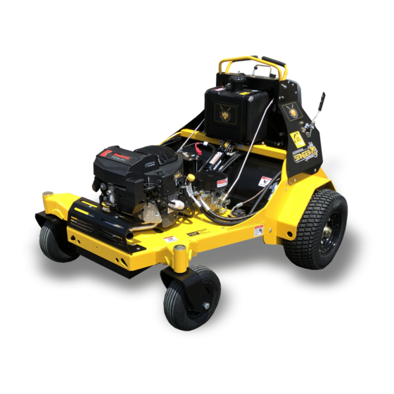
- Page 1 Quad-Aer Operator’s Manual Need Help? Factory Support: 502-536-0716...
- Page 2 Introduction Thank you for purchasing this Stinger Equipment, Inc. product. This manual will explain the safety, maintenance and operation of your unit. Safety • All operators should read the product manual in its entire- ty before operating. All operators must be properly trained on the controls and their functions.
-
Page 3: Signal Word Definitions
This Symbol means: ATTENTION! TAKE NOTICE! Your attention is needed to ensure your safety and the safety of those around you. This symbol is fol- lowed by a Signal word describing the level of hazard. Through- out this manual and on all equipment you will see these safety labels. -
Page 4: Maintenance
Maintenance Turn the unit off and remove key. Disconnect the negative battery cable and remove spark plug before performing any maintenance. Hydraulic System • Hydraulic Fluid level should be checked daily. Hydraulic Fluid Level Check Procedures. Place unit on level ground. Locate the Site Glass on the hydraulic tank. - Page 5 Hydraulic Fluid and Filter Change Procedures: Remove thigh pad. Clamp return line above the filter with a pair of smooth tooth lock- ing pliers. See figure 2. Remove Hydro Filter. Remove locking pliers and catch oil in a 13+ quart container and properly recycle or dispose of according to your local laws.
- Page 6 Belt Inspect the engine belt every 200 hours for signs of wear. Main Belt and Auxiliary Belt Replacement Procedure: Loosen idler pulley bolt to release belt pressure. The timing belt has a secondary bolt that needs to be loosened to allow the ten- sion arm to swing freely.
-
Page 7: Tracking Adjustment
Tracking Adjustment Forward Adjustment Slide rod end clip up (figure 5) and gentle pull rod away from hydrostatic motor Turn rod end clockwise or counter clockwise to increase or decrease speed on that side. Figure 5 Reverse Speed Limiter Loosen bolt as shown in figure 6 and slide stop forward or back- wards to decrease or increase reverse travel speed prospectively. -
Page 8: Unit Operation
Unit Operation Starting and Stopping the Engine Pull choke knob up to apply the choke. Used typically when engine is cold. Figure 7. If equipped with EFI skip this step. Turn ignition key to position II until engine starts and release the key. - Page 9 Tines The tine Position switch as shown in figure 8, allows for 2 different oper- ating styles and the ability to lock the tines in the up position for transport. In the UP position the tine assembly will remain up unless the foot pedal depressed.
- Page 10 Unit Operation Put operator platform down! Step on platform careful not to hit the foot switch. DO NOT OPERATE UNIT WITH PLATFORM IN THE UP LOCKED POSITION! Serious bodily harm can occur. Release Parking brake as shown in figure 10 . Tire damage can occur if parking brake is not released.
- Page 11 Figure 11 Always consider what might be below the turf prior to aerating. Does the property have unground utilities, invisible dog fence, low voltage lighting, irrigation., etc.? Calling 811 or a private locate services is strongly recommended and maybe the law. Take appropriate actions to prevent damages...
- Page 12 www.StingerEquipment.com 2140 Spencer Court LaGrange, KY 40031 (502) 536-0716...
Need help?
Do you have a question about the Quad-Aer and is the answer not in the manual?
Questions and answers
How do we put the unit in neutral