
Summary of Contents for Juxta VJ77
- Page 1 User’s Manual Model VJ77 PC-based Parameters Setting Tool (with Model L4506HA Dedicated Adapter) IM 77J01J77-01E IM 77J01J77-01E 9th Edition...
- Page 3 User Registration Request Thank you for purchasing YOKOGAWA products. Please register to the following Partner Portal Member Site. You can use various services such as confirmation of purchased product information, download of related materials, and newsletter. https://partner.yokogawa.com/global/...
-
Page 5: Introduction
Describes how to print parameter or program data. Chapter 9 Monitoring Input/Output Values Describes how to monitor the I/O values of JUXTA or YS80 instruments and how to view the result of self-diagnosis. Chapter 10 Input and output adjustment Describes how to adjust JUXTA or YS80 instruments’... - Page 6 Intended Readers This manual is intended for people familiar with the functions of JUXTA signal conditioners or YS80 series rack insturuments and capable of working with Windows, such as instrumentation and control engineers and personnel in charge of maintaining instruments and control equipment.
-
Page 7: Visual Inspection And Cross-Check Of Accessories
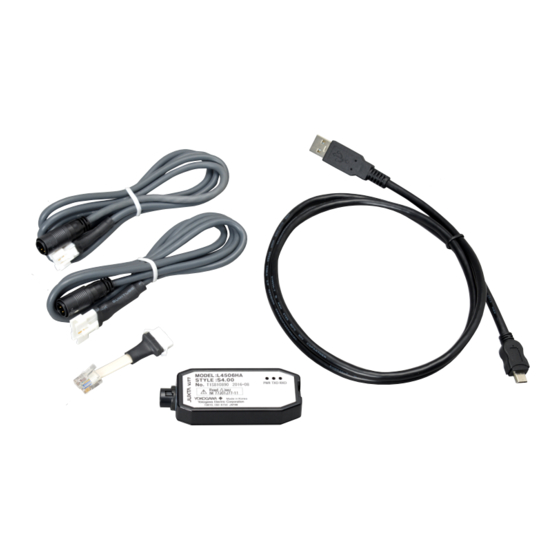
Dedicated adapter (Model: L4506HA) 1 unit MicroUSB(USB2.0) cable (Part no.: A1590WL) 1 cable JUXTA communication cable with 3-pin connectors (Part no.: F9182ED) 1 cable JUXTA communication cable with 5-pin connectors (Part no.: F9182EE) 1 cable Modular jack conversion adapter (Part no.: E9786WH) -
Page 8: Documentation Conventions
Click Options. written in boldface. From the File menu, choose Exit. Type JUXTA in the Model box. Characters to be typed by the user via keyboard are written in monotype font. IMPORTANT Indicates that operating the hardware or software in a particular manner may damage it or result in a system failure. -
Page 9: Notice
Notice Regarding This User’s Manual (1) This manual should be passed on to the end user. Keep this manual in a safe place. (2) Read this manual carefully to gain a thorough understanding of how to operate this product before you start using it. (3) This manual is intended to describe the functions of this product. - Page 10 Exemption from Responsibility (1) Yokogawa does not make any warranties regarding the product except those mentioned in the WARRANTY that is provided separately. (2) Yokogawa assumes no liability to any party for any loss or damage, direct or indirect, caused by the use or any unpredictable defect of the product. (3) Be sure to use the spare parts approved by Yokogawa when replacing parts or consumables.
-
Page 11: License Agreement For Package Software Product
(1) The terms and conditions of this Agreement shall apply to the following package software of Yokogawa (herein after referred to as “Package Software Product”. Product: VJ77, Parameters Setting Tool and materials related thereto that Yokogawa designates Number of license: One (1) (2) The Package Software Product herein shall include; without limitation, a software program, font, data base, data put into fill-in-the-form, instruction manual,... - Page 12 viii (5) Under separate maintenance contract, Yokogawa may conduct maintenance service for the Package Software Product, at the expense of you even after the Warranty period. The maintenance service for the Package Software Product shall be classified into those of standard software, customized software. Standard Software Standard Software herein means the standard package software covered by Yokogawa’s Catalogue and/or General Specifications. The maintenance service for Standard Software may be available for the latest two versions unless otherwise covered by Yokogawa’s Catalogue and/or General Specifications. However, the maintenance service for the Package Software Product which is the earlier version among the latest two versions may be available only for five (5) years after the last up-dated. The maintenance service for the version of the Package Software Product declared by Yokogawa to discontinue order acceptance may be available for five (5) years after such declaration. Customized Software Customized Software herein means the software customized by Yokogawa pursuant to the Quotation or Functional Specifications agreed by both parties. The maintenance service for the Customized Software shall not be available to you including your customer after the Warranty Period unless otherwise separately agreed by both parties. However, such maintenance service may be conducted at your expense as remodeling contract agreed by the both parties.
-
Page 13: Table Of Contents
Visual Inspection and Cross-check of Accessories ..........iii Documentation Conventions ................... iv Notice........................... v LICENSE AGREEMENT FOR PACKAGE SOFTWARE PRODUCT ...... vii VJ77 PC-based Parameters Setting Tool ...........1-1 An Overview of VJ77 and Its Functions ............. 1-1 1.1.1 What is VJ77? ..................1-1 1.1.2 Functions....................1-1 Conceptual View of VJ77 .................. - Page 14 6.1.1 Uploading Parameter Data from Device ..........6-1 6.1.2 Opening a Parameter File ..............6-2 6.1.3 Uploading Program Data from JUXTA Instrument ........ 6-2 6.1.4 Opening a Program File ................. 6-2 Downloading Data to JUXTA Instrument ............6-3 6.2.1 Downloading Parameter Data to Device ..........6-3 6.2.2...
-
Page 15: Vj77 Pc-Based Parameters Setting Tool
Uploads parameters or program from a microprocessor-based JUXTA instrument to a personal computer, and downloads the parameters and program once loaded or a program you created, to a JUXTA instrument. It also enables you to read and write parameters to and from the YS80. You can also write to a YS80 even it is of a different style. -
Page 16: Conceptual View Of Vj77
Upload from/download to JUXTA or YS80 ALM1 ALM2 (Pier-to-pier communication) Reference to Set parameters/ parameters Set programs Adjust (only for JUXTA) Instrumens Read from/Save to a disk Hard disk Figure 1.2.1 Conceptual View of VJ77 PC-based Parameters Setting Tool IM 77J01J77-01E... -
Page 17: Operating Environment And Wiring Specifications
Insulation resistance: Minimum of 100 M/500 V DC between USB communication port and the JUXTA connection sides. Dielectric strength: 500 V AC/minute between USB communication port and the JUXTA connection sides. Ambient temperature: 0 to 50°C Ambient humidity: 5 to 90%RH (no condensation) Transport and storage conditions: -40 to 70°C, 5 to 95%RH (no condensation) -
Page 18: External View Of Dedicated Adapter
1.4 External View of Dedicated Adapter Unit: mm 1150±25 985±35 (78.4) 3-pin connector 1095±20 (70.2) MicroUSB cable 5-pin connector Modular-jack Communication cable conversion 78.4 70.2 Figure 1.4.1 Dedicated Adapter EMC Standards Moel L4506HA EMC directive: EN 61326-1 compliance, Class A Table 2 EN 55011 Class A Group 1 EMC Regulatory Arrangement in Australia and New Zealand (RCM): EN 55011 Class A, Group 1 KC marking: Electromagnetic wave interference prevention standard, electromagnetic wave... -
Page 19: Precautions When Communicating With Device
Precautions When Communicating with Device NOTE Do not remove the communication cable while communicating with a JUXTA or YS80 instrument. Communication may be in progress in the following windows. • Communication execution window • Parameter setting window • Parameter view window • Program setting window • Parameter Setting dialog box... - Page 20 Blank Page...
-
Page 21: Setup
Setup This chapter describes how to set up the hardware and software required to run VJ77. First, download the necessary software and driver from the website. Next, install the USB driver to allow the use of a USB cable. Finally, install the VJ77 PC- based Parameters Setting Tool. Downloading the Software and Driver Download VJ77 PC-based Parameters Setting Tool and USB Converter Driver Software from the following URL. Download files are in zip format. - Page 22 Step 2 In the User Account Control screen, click Yes. Step 3 In the VJ77 USB Driver for Windows 10 Setup screen, click Install. Step 4 In the Finished screen, click Close. This completes the installation of the driver. Connect the dedicated cable to the PC’s USB port to automatically start using the cable.
- Page 23 ■ Checking the Installation of the USB Driver Step 1 With the adapter connected to the dedicated cable, connect the dedicated cable to the PC. Step 2 For Windows 10; In the Windows search bar, type Device Manager and then click Device Manager in the pop-up window.
- Page 24 Click VJ77 USB Driver for Windows 10, and then click Uninstall. Step 4 If the User Account Control screen appears, click Yes. Step 5 In the VJ77 USB Driver for Windows 10 Setup screen, click Uninstall. Step 6 In the Uninstall Finished screen, click Close. This completes the uninstallation.
- Page 25 For Windows 8 Step 1 Connect the dedicated cable to the PC. Step 2 Hold down the Windows key and press X, and then click Device Manager in the list. Step 3 Right-click “USB Serial Port (COMn)” under “Ports (COM & LPT),” and click Uninstall.
- Page 26 Step 5 Right-click “USB Serial Converter” under “Universal Serial Bus controllers,” and click Uninstall. Step 6 A device uninstallation confirmation window appears. Select the “Delete the driver software for this device” check box, and click OK. This completes the uninstallation. IM 77J01J77-01E...
-
Page 27: Installing Vj77
Double-click the downloaded zip file to extract the files. Step 2 Double-click setup.exe in the unzipped folder to start a setup wizard. Follow the instructions in the dialog boxes. When installation is complete, VJ77 will be registered under All Programs in the Windows Start menu. Uninstalling VJ77 Step 1 For Windows 10; In the Windows Start menu, click Start > Settings > Apps >... -
Page 28: Connecting Instrument To Personal Computer
Connecting Instrument to Personal Computer This section describes how to connect a JUXTA or YS80 instrument to a personal computer. 2.5.1 Items Required for Connection To connect a JUXTA instrument to a personal computer, the following are required: (1) Personal computer with VJ77 installed (2) MicroUSB(USB2.0) cable... - Page 29 Modular-jack JUXTA communication cable conversion adapter Dedicated adapter for VJ77 (L4506HA) YS80 Series Rack instrument MicroUSB (USB2.0) cable Example of connecting to the YS80 series IM 77J01J77-01E...
-
Page 30: Setting The Communication Port
2-10 Setting the Communication Port This section describes how to set the communication port to connect a JUXTA or YS80 instrument to the personal computer (VJ77). The communication port (serial port) indicates the valid serial port that the PC is using when a communication execution window is open. -
Page 31: Basic Operation
Starting VJ77 From the Windows Start menu, choose the commands in the following sequence. Start > Programs > VJ77 > VJ77 Setting Tool Or, double-click the shortcut (VJ77 Setting Tool). VJ77 starts up, and the main window appears. Quitting VJ77 From the File menu, choose Exit. Or, click × in the upper right of the window. -
Page 32: Window Elements And Functions
Shows the menu items read from the JUXTA or YS80 instrument. Submenu button Shows the submenu items of the selected parameter menu. Command area Shows the commands that can be used on VJ77. The commands are arranged by parameter or program type. IM 77J01J77-01E... -
Page 33: Basic Operation
CONST display area: Constant Setting dialog box (2) In the Parameter Setting dialog box, after entering data, clicking WRITE updates the data. Some types of data require you to enter values in text boxes while others require you to select from drop-down lists. NOTE If you click Close without clicking WRITE, any data typed in the text box will not be written to the JUXTA instrument. Be sure to click WRITE after you enter data. (3) In the Program Editor and Constant Setting dialog boxes, after entering data, clicking Enter applies the data in the program display area. Writing to the JUXTA is executed using the Program Download command. IM 77J01J77-01E... -
Page 34: Operation Using Keyboard
3.4.2 Operation Using Keyboard Menu bar operation (1) Press the F10 or ALT key on the keyboard. File in the menu bar is displayed as a button, indicating that it is selected. Move to the menu item you wish to execute using the RIGHT ARROW and LEFT ARROW keys, then press the ENTER, UP ARROW, or DOWN ARROW key. -
Page 35: Main Windows And Their Functions
Main Windows and Their Functions 3.5.1 DISPLAY Menu Window This window shows the input/output values of the JUXTA or YS80 instrument and the results of self-diagnosis. See Also For more information about the DISPLAY dialog box, see Chapter 9, “Monitoring I/O Values.” 3.5.2 SET Menu Window This window is used to set various parameters of the JUXTA or YS80 instrument. -
Page 36: Adjust Menu Window
3.5.3 ADJUST Menu Window This window is used to adjust the I/O of the JUXTA or YS80 instrument. See Also For more information about the ADJUST dialog box, see Chapter 10, “Input and output adjustment.” 3.5.4 Program Setting Window This window is used to create/edit programs for JUXTA computing units. Model Selection button Clicking Model Selection selects the model name of a JUXTA computing unit. - Page 37 CONST (constant) display area* Shows constants for the specified program. *: When Program Upload is executed and the Program Editor dialog box is displayed, these cells show the program and constants uploaded from the JUXTA instrument. Insert Row button When a line is selected in the program display area, clicking this button inserts a line above the selected line. Delete Row button When a line is selected in the program display area, clicking this button deletes the line.
- Page 38 Blank Page...
-
Page 39: Setting Parameters
Click OK if ready. The parameter setting window appears. If connected via the DSC or DSC2 port of the JUXTA D series, carry out Step 4. Step 4 When connected via the DSC or DSC2 port of the JUXTA D series, the SLOT No. Setting dialog box appears. Enter the slot number you wish to... -
Page 40: Setting Parameters
In the same way as Step 1 to Step 3, set the 100% value of the input range by double-clicking the data cell of D25: INPUT1 H_RNG. The input range of the connected JUXTA instrument has now been changed from 1 to 5 V DC, to –10 to +10 V DC. -
Page 41: Notes On Setting Juxta Parameters
4.2.2 Notes on Setting JUXTA Parameters The input range/output range of a JUXTA instrument can be set in two ways, depending on the model of the instrument. (1) Models for which 0% and 100% values of the range are set: The high range limit and low range limit are represented as L_RNG and H_RNG, as in INPUT L_RNG and INPUT H_RNG. -
Page 42: Selecting An Item From A List Box And Writing It To Device
In the parameter setting window, click SET and then SET(I/O). The SET(I/O) submenu window appears. Step 2 Double-click the parameter D07: SENSOR TYPE. A Parameter Setting dialog box appears. Step 3 Click the arrow button (▼) next to the text box, select TC from the list which opens, and then click WRITE. The change you made is written to the JUXTA instrument. IM 77J01J77-01E... -
Page 43: Setting A Program (Juxta Only)
Setting a Program (JUXTA only) This chapter describes the procedure to set a program for a JUXTA instrument via the program setting window. See Also When setting programs, refer to the parameter lists given in the documentation for the respective JUXTA computing units. For details about creating a program, see the Technical Information documents for the respective programmable computing units (document No. -
Page 44: Opening Program Setting Window
Opening Program Setting Window Step 1 Start VJ77. Step 2 Click Create Program. The program setting window appears. See Also For operations after selecting Upload Program Data from Device or Read Program Data from a File, see Chapter 6, “Uploading and Downloading.”... -
Page 45: Setting A Program
Setting a Program 5.2.1 Creating a New Program The following is an example of the procedure to set a moving average computation (of the last 100 seconds) for a VJX7 free program. NOTE • When setting a program, be sure to click Model Selection button to select a model (see Step 2 in the following procedure). Selecting a model name updates the contents of the STEP and CONST columns accordingly. - Page 46 Step scroll bar STEP Program text box Comment text box Shows/hides the command help Command group button When the command help is shown Command list display area Step 4 Click the program text box under STEP:G01, type LDX1, and then click Enter. Like step 4, enter LDH1 for G02, MAV for G03, STY1 for G04, and END for G05. Step 5 Then, click Enter.
- Page 47 JUXTA computing units. IMPORTANT DO NOT change a program for a computing unit of the JUXTA F series and JUXTA W series other than programmable computing units. In case the unit is operated on the computing function with program changed after factory-ship, the operation will not be guaranteed.
- Page 48 To check the syntax of the program you created or modified: Click Command Check. NOTE • The Command Check function is disabled when setting up the program of any model whose name is not listed in the Model Selection dialog box. • The Command Check button is used to check the spelling of operation codes and whether the number of steps exceeds the limit. A dialog box appears when an error is found: To copy program code, comment, or constant to another cell: Select a cell or characters and press the keys.
-
Page 49: Converting Free (User) Program Automatically
Converting Free (User) Program Automatically This section explains how to convert old style MXS free (user) programs to those for the new style MXS. Step 1 Upload free (user) program data from the JUXTA (see Section 6.1.3 for details on the uploading procedure). Step 2 In the Program Editor dialog box, click the Model Selection button. Step 3 In the Model Selection dialog box, select a new style MXS and click the OK button. - Page 50 Blank Page...
-
Page 51: Uploading And Downloading Data From/To Device
Click OK to upload data from the JUXTA or YS80 instrument. A parameter view window appears. If connected to DSC or DSC2 of the JUXTA D series, the SLOT No. Settings dialog box appears. Set the slot number (1, 2, 3…15, 16 from left to right as you face the D series), and then click OK. -
Page 52: Opening A Parameter File
Click OK to upload data from the JUXTA instrument. A program setting window appears. NOTE Only constants (CONST) are displayed for a computing unit other than programmable computing units of the JUXTA VJ series, JUXTA M series, and WXT. See Aiso For the how to create and modify a program in the Program Editor dialog box, see Chapter 5, “Setting a Program.”... -
Page 53: Downloading Data To Juxta Instrument
If connected to DSC or DSC2 of the JUXTA D series, the SLOT No. Settings dialog box appears. Set the slot number (1, 2, 3…15, 16 from left to right as you face the D series), and then click OK. NOTE VJ77 only downloads the data shown in the SET menu window. Data shown in the DISPLAY or ADJUST menu window is not downloaded. IM 77J01J77-01E... -
Page 54: Downloading A Program To Device
NOTE • Data in the Comment cells are not downloaded. • A created program downloaded to the JUXTA computing unit other than programmable computing units is not downloaded and only constants are downloaded. The “Error found during command check. Do you want to see the error content?” appears if the program contains any syntax error or other kind of error. Clicking Yes opens the... -
Page 55: Saving Data
Saving Data This chapter describes how to save to disk the parameter/program data that was uploaded or you created. Parameter data and program data will be saved with the following filename extensions: • Parameter data files: ********.7pm • Program data files: ********.7pg • Filename extension of CSV files: *.csv Saving Parameter Data to Disk Step 1 Follow the instructions in Section 6.1, “Uploading Data to Your PC” to upload parameter data. - Page 56 Blank Page...
-
Page 57: Printing Data
Printing Data This chapter describes how to print the parameter or program data. Printing Data Step 1 To print parameters, click Print in the parameter view window. To print the program, click Print in the Program Setting window. A Print Range dialog box appears. Printing parameters Printing a program Step 2 The Print dialog box appears. You can select the ranges of items to be printed by selecting and clearing the check boxes. Then, click Print to start printing. -
Page 58: Previewing The Print Image
Previewing the Print Image This section describes how to view the print image. Step In the Print Range dialog box, click Print Preview. A Print Preview dialog box appears. If there are multiple pages, you can use the scroll bar to turn the displayed page. Close the Print Preview dialog box to return to the parameter view window or Program Setting window. IM 77J01J77-01E... -
Page 59: Monitoring I/O Values
You can monitor this information via the DISPLAY menu window. 9.1 Opening the Monitor Dialog Box The following is an example using JUXTA. Preparation Connect the JUXTA instrument to the personal computer, then turn on the power to the instrument. Step 1 Start VJ77, and click SET in the main window. The communication execution window appears Step 2 Click Parameter Setting. - Page 60 The DISPLAY1 page or the DISPLAY dialog box without a tabbed page shows the conditions at the time of communication. However, the DISPLAY2 page updates its display contents in approximately 5-second intervals (periodic upload for updating). When DISPLAY or DISPLAY1 appears, to update the data, click another parameter menu selection button or submenu selection button, and then click the DISPLAY button. To stop the periodic upload for updating of the DISPLAY2 page, click READ STOP.
-
Page 61: Input And Output Adjustment
10-1 Input and output adjustment This chapter describes how to use VJ77 to monitor input/output values of a JUXTA or YS80 instrument and how to set wire resistance compensation. JUXTA adjustments are made in the ADJUST menu window of the Parameter Setting window. -
Page 62: Performing Fine Adjustment Of Input
10.2.2 Adjusting the Input Span Apply the 100% level of the input to the JUXTA instrument. If the signal level after A/D conversion in the JUXTA instrument (the value displayed in the P05: IN1 SPAN ADJ data cell) and the actual input signal level do not match, you must correct the input span. The procedure is the same as above. -
Page 63: Correcting The Output
This section describes how to perform corrections of outputs. The following shows an example when doing so for a JUXTA VJH7 isolator. For wiring with a calibrator or other apparatuses, see the user’s manuals for respective JUXTA or YS80 instruments. Step 1 Double-click the P30: OUT1 ZERO ADJ data cell and click WRITE. The 0% level is then forcedly set to the output regardless of the input level. -
Page 64: Setting Wire Resistance Compensation
10-4 10.4 Setting Wire Resistance Compensation This section explains how to perform wiring resistance correction using JUXTA VJU7 (S4) as an example. For wiring details, see the relevant JUXTA or YS80 user’s manual. If the input wiring resistance is causing a significant error after the wiring to the field device has been completed, you can compensate for the wiring resistance with the following procedure. Change the wiring connections in the field as shown at the bottom of this page. Step 1 When the input is stable, double-click the P01: WIRING R data cell. Step 2 Click the arrow next to the text box. Choose EXECUTE from the list and click... -
Page 65: Using The Forced Output Function
To output the 100% value forcedly for example, type 100 and click WRITE. The 100% value is then output. The ADJUST menu window for some models of JUXTA does not have the TEST sub menu window on which you can forcibly set an output level. Even with such models however, it is possible to output 0% and 100% levels forcedly by the same procedure as that used for output correction. - Page 66 Blank Page...
-
Page 67: Troubleshooting
Check whether your display meets these conditions. Communications not Your USB drivers may be Download and install the latest VJ77 USB working out of date. drivers from the download site. Communications not COM port settings may Check the COM port in the Windows Device working be incorrect. - Page 68 Blank Page...
-
Page 69: Revision Information
Revision Information Title : Model VJ77 PC-based Parameters Setting Tool Manual No. : IM 77J01J77-01E Dec. 1999/1st Edition Newly published Jan. 2004/2nd Edition Supports Windows 2000 and XP. June 2004/3rd Edition Change of the company name. July 2005/4th Edition Addition of new style product and automatic conversion function of free programs. - Page 70 YOKOGAWA ELECTRIC CORPORATION Headquarters 9-32, Nakacho, 2-chome, Musashino-shi, Tokyo, 180-8750 JAPAN Phone : 81-422-52-5555 Branch Sales Offices Osaka, Nagoya, Kurashiki, Hiroshima, Fukuoka, Kitakyusyu YOKOGAWA CORPORATION OF AMERICA Head Office 12530 West Airport Blvd, Sugar Land, Texas 77478, USA Phone : 1-281-340-3800 Fax : 1-281-340-3838 Georgia Office 2 Dart Road, Newnan, Georgia 30265, USA Phone : 1-800-888-6400 Fax : 1-770-254-0928...
Need help?
Do you have a question about the VJ77 and is the answer not in the manual?
Questions and answers