Advertisement
Quick Links
Advertisement

Related Manuals for DINDAN 40ACU/004-3

Summary of Contents for DINDAN 40ACU/004-3
- Page 1 Enclosure cooling unit Model 40ACU/004-3 User's guide...
-
Page 2: Table Of Contents
Contents Page 1. Over view 2. Specification 3. Notification 4. Technical information 9-10 5. Installation 11-19 6. Maintenance 7. Fault indication 8. Assembly and parts number... - Page 3 Introduction Cooling unit for control cabinet is used for diminishing internal heat by providing cool air to the control cabinet that can protect sensitive equipment It is specially designed to resist surrounding temperature as high as 40-50 C and can function well in any factories including those with intensive dust, particles and oil mist or with high acidity.
-
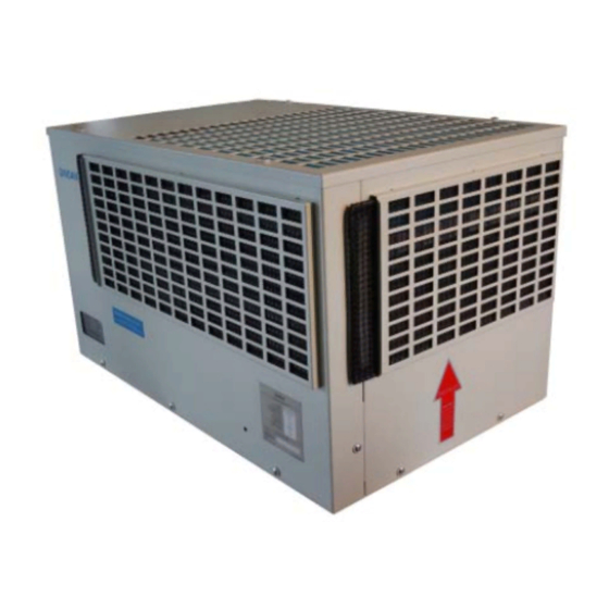
Page 4: Over View
1. Over view 40ACU/004-3... - Page 5 แผ่ น กรองฝุ ่ น (Filter) แผงระบายความร้ อ น (Condensor coil) พั ด ลมระบายความร้ อ น (Condensor fan) แผ่ น กรองฝุ ่ น พั ด ลมส่ ง ความเย็ น แผงควบคุ ม (Filter) (Evaporator fan) (Hiprosent control) แผงทำความเย็ น ถาดน้ ำ ทิ ้ ง คอมเพรสเซอร์...
- Page 6 HIPROSENT CONTROL (EHE015-5) LED2 LED1 LED3 Hi-Lo Voltage Control 220V 50/60Hz Main connection from 10A BREAKER supply by Customer Control and Monitor A1 = Main controller SW1, SW2 = Temperature adjustment D1 = Temperature display LED1 = Condensing temp. over heat LED2 = Unit is working LED3 = Power on Cable and signal...
-
Page 7: Specification
2. Specifications Characteristics (under normal operating condition at ambient temp. +35 40ACU/004-3 Model Capacity W. 1500 Installation type Input single-phase (V.) 220V+20% / -15% frequency (Hz.) 50/60 current (A.) 3.60 Compressor hermetic type reciprocate torque start type high refrigerant type 134A lock rotor (A.) - Page 8 20-1/8" Drills 105.5 105.5 320 390 Cutting area Templet for drill & cutting Ambient Air In Ambient Air In Warm Air Out LEFT FRONT RIGHT REAR Cold Air Out Return Air In 52.3 313.5 32.5 BOTTOM...
-
Page 9: Notification
3. Notification Before, drilling, and cut. should use clean dry cloth, or the inventory doesn’t lead the electricity, covers the equipment for protects iron dust touches the electrical equipment while installing. (In case of machine still operate.) Cooling unit should be installed in the good circuration area Check vertical and horizontal level of which their error shall be allowable within +/- 2 o in order to facililate efficient drainage Should always install gasket between Installation plate and Cooling Unit... -
Page 10: Technical Information
General Condition Storage: Cooling unit should be stored at temp not exceeding 70 Transportation: This type of cooling unit can't be laid down horizontally. Installation: It shall be installed in vertical direction only (please see figure below) CORRECT INCORRECT Disposal of damaged Cooling Unit As its refrigeration system contain Refrigerant and lubricating oil for compressor, in order to protect environment, these substances should be disposed of properly or other under direction given by distributor. - Page 11 Refrigernation Cycle Condenser Filter Compressor dryer External Internal Cap.tube Evaporator Drainage Drainage of condensed water from cooling system shall be done by inserting drain tube under drainpan (see page 19) and trying not to left it twisted. Make sure, the other end of drain tube is not lower than water level in the container, in order to avoid water reflux Drain tube Drain tube...
-
Page 12: Installation
5. Installation Accessories for 40ACU/004-3 Parts Quantity Cooling unit ADAPTER (installation base) User's guide & Warranty card Elbow 90 Liquid gasket Air filter 182x340 mm. Air filter 182x488 mm. 1/2'' drain tube 200 cm. (for secondery drain) 1/2'' drain tube 250 cm. (for primary drain) Self tapping screw 1/8'' x 3/8'' (for Installation base) 30 Plain washer (for M6 x 20 mm. - Page 13 Installation procedures 1. ADAPTER overview 2. Loose 4 screws from each corners 3. Take off the upper part from the lower part...
- Page 14 4. Locate the lower part (FRONT-LOWER) of ADAPTER on the position that you want to install the cooling unit 5. Layout as templet - for fix the lower part to the control cabinet (FRONT-LOWER)20 drills (1/8"hole) - for cooling air circulation port (inside rectangle)
- Page 15 6. Cover equipment in cabinet with clean dry cloth, or the inventory doesn’t lead the electricity, and cover with paper box at position will be drilling and cutting in order to prevent metal scrapt falling in cabinet. (see figure below) Paper Box 7.
- Page 16 8. File to eliminate sharp edges 9. Apply the LIQUID GASKET round the air circulation port, in order to protect water into control cabinet...
- Page 17 10.Carefully locate lower part(FRONT-LOWER) on the cooling air circulation port and tighten 20 screws until LIQUID GASKET appear to outside 11.Place the upper part (FRONT-UPPER) on the lower part (FRONT-LOWER)
- Page 18 12.Very importance for this step, tighten 4 screws from (2), while adjust level and incline angle for appropriate water flow direction to water drain pipe 13.Stick foam tape, strat at position No.1 and end at position No. 2 (TOP VIEW) Front...
- Page 19 15. Place the cooling unit on ADAPTER. be sure control panel on front and drainpipe on rear 14. Mounting 4 sets of screws, size M6 x 20 mm. with washer into the Rivet nuts, which are positioned under the cooling unit. M6x20mm.
- Page 20 16.Drainage system Figure demonstrating installtion of drain tube 150 cm. Note 1 cooling unit 2 control cabinet 3 primary drain hose 4 secondary drain hose 5 abnormal, water flow out of the secondary drain hose, please call service! 6 normal,water flow or not flow out of the primary drain hose depends on ambient humidity and air leakage into the control cabinet 7 condensate drain tank.
-
Page 21: Maintenance
6. Maintenance Maintenance of DINDAN cooling unit can be simply done by giving care to the air filter and condensor coil not to be clogged up. The cleaning interval for the air filter depends on how dirty it is of the area where it is installed. -
Page 23: Assembly And Parts Number
8. Assembly and part number ITEM DESCRIPTION PART NUNMBER Qty. servo fan EP-03-012 compressor EP-04-008 control board XEE-22-502 filter mat CR-15-002 filter mat CR-15-001...
Need help?
Do you have a question about the 40ACU/004-3 and is the answer not in the manual?
Questions and answers