Table of Contents
Advertisement
Quick Links
Advertisement
Table of Contents

Related Manuals for Solarbayer BioX Series


Summary of Contents for Solarbayer BioX Series
- Page 1 Operating Instructions Wood log boiler Wood log boiler BioX 15-45...
- Page 2 DIN VDE 0100: installation of low-level electric systems; installation of power plant systems DIN VDE 0105: run of electrical systems *This list have no right on completeness, actuality and new publication. © Solarbayer GmbH [210205]...
-
Page 3: Table Of Contents
(manual) ..........46 10.3 Cleaning combustion Overview safety equipment ..36 chamber ..........46 10.4 Cleaning the flue pipe ....... 47 10.5 Filling shaft – Filling shaft door ..47 10.6 Checking the heat exchanger ..47 © Solarbayer GmbH [210205]... -
Page 4: Directory
Wiring instructions ......67 13.6 Connections ........69 Emission measurment ....70 14.1 Measurement notes......70 14.2 Preparing the measurment ....70 14.3 Creating a measurement condition (continuous operating state) .... 70 14.4 Performing a measurment ....70 © Solarbayer GmbH [210205]... -
Page 5: Safety Notes
Please look up in these instructions anything about which you are unsure. Ensure that you understand the instructions in this manual and that you are sufficiently informed about the functioning of the biomass furnace system. Solarbayer is at your disposal at all times for any questions. ... -
Page 6: Warning Notes
People (including children) who are not in a position to use the equipment safely due to their physical, sensory or mental capacities or their inexperience or lack of knowledge should not use this equipment without supervision or instruction by a responsible person. © Solarbayer GmbH [210205]... -
Page 7: Operation And Maintenance
Solarbayer factory customer must be immediately switched service. off using EMERGENCY OFF. -
Page 8: Cover Installation Biox - Wood Log Boiler 15 - 45
Back cover behind top Exhaust blower Front cover top Nut´s for vertical position Front cover middle Elevation screw for high adjustment Front cover bottom Front door (optional) Fixing plates for hinges of the front door (optional) Top cover front © Solarbayer GmbH [210205]... -
Page 9: Installation, Boiler Room And Supply Air
Crosstip screwdriver Screwdriver for slotted screws (short) Fixed spanner (17/13/10/8) Allan wrench (8/6/5/4/3) Torx wrench (T20) Wire cutter You can also use a ratchet and a cordless screwdriver for the installation. © Solarbayer GmbH [210205]... -
Page 10: Adjust Of The Doors
With the elongated holes, you can take the screws on the right position. (look at +). © Solarbayer GmbH [210205]... - Page 11 Put the boiler in the right position with a level (the wood log boiler can drop down to the front side, just in case if incurred condensate). © Solarbayer GmbH [210205]...
- Page 12 10. screws torx each side) DON´T lock the screws. Please, lay the plate of the display and the screws separately. The cut-outs in the side covers are for the cable fairlead on the backside. © Solarbayer GmbH [210205]...
- Page 13 „visible in front“ self-tapping screws) Take the cable straps in the first notches to have enough scope for Please, look at the correct position of the installation. the switch (picture at the top). © Solarbayer GmbH [210205]...
- Page 14 (point 5+10) and door) the front covers (point 14), to can Otherwise go to point 10 move the side covers. Tip: You can order and install this later, too. © Solarbayer GmbH [210205]...
- Page 15 Open all doors to save the door switch against damage. Following, ATTENTION! lock the screws of the side cover (4 Use only the outside fix holes! The self-tapping screws, picture) inside holes are for the back covers. © Solarbayer GmbH [210205]...
- Page 16 Wide cover WITHOUT long profile = middle Wide cover WITH long profile = bottom BioX 25-45: Wide cover = top Slim cover WITHOUT long profile = middle Slim cover WITH long profile = bottom Following remove the cable straps of „point 7“ © Solarbayer GmbH [210205]...
- Page 17 Dismount the stopping plate. CLEANER (optional equipment) Dismount the screw of stopping and the holding. Open the cleaning cap and remove the safety bolt of the turbolators. Otherwise further with point 17 Tip: You can mount it later, too. © Solarbayer GmbH [210205]...
- Page 18 Insert the turbolators and fix it with side. Take automatically at the exhaust room. (3 screws) the bolt on the shaft. Following turbolator cleaner in the right position. mount the cleaning cover on the exhaust room. © Solarbayer GmbH [210205]...
- Page 19 (above the joint with the Look after a good cable routing! rounded head) Demount the STL-protection cap, insert the STL through the front cover, check the position and fix it (look also at point 18). © Solarbayer GmbH [210205]...
- Page 20 Also you can insert the clamp X5 panel of the display! and X2 of the display board and X12 on the control board. IMPORTANT! Look therefor at the electric documentation! © Solarbayer GmbH [210205]...
- Page 21 Following fix the nuts for the vertical attitude. (look at point 20, number) © Solarbayer GmbH [210205]...
- Page 22 (90°, 135°, 180°, look introduction at the package of the blower) IMPORTANT! Fix all nuts of the holding bows. Make a leak test, when you start the wood log boiler at the first time. © Solarbayer GmbH [210205]...
- Page 23 Also you have to connect the have more tanks, power connection on the backside schema of the wood log boiler. (it isn´t include in the shipment) You don´t have thermometer pockets, you can also use PT1000 pull up sensors. © Solarbayer GmbH [210205]...
- Page 24 Adjust as long the pressure senders that appears the “failure 13!” on the display, when min. one of the doors are open. Therefore, you slack the lock nut and turn the pressure senders more out/in the door with an Allan key. © Solarbayer GmbH [210205]...
- Page 25 8 screws M8. Please, cover front (2 screws). check the right position of the panels. You have finished the mount of the Normally there are panels inside covers, when you have the standard the wood log boiler! model. © Solarbayer GmbH [210205]...
- Page 26 (4 x M4 x 20 Allan key). to far away or to near of the covers. Attention the clearance between the front door and the side covers. © Solarbayer GmbH [210205]...
- Page 27 (look at point 10, picture on the other side. covers and fix the door switch on the +). other side (look at the picture on Take all doors off about the door step 8) hinges. © Solarbayer GmbH [210205]...
- Page 28 (Allan key size 8), turn it 180° and heating door. around and fix them on the doors This get explained in the following again. points. ATTENTION! Do this on all three doors! © Solarbayer GmbH [210205]...
- Page 29 Cover installation BioX – wood log boiler 15 – 45 Following, remove the seal outside. Pull out the element of the inner Remove the 6 screws (3 on the top isolation. and 3 on the bottom) of the inner lining. © Solarbayer GmbH [210205]...
- Page 30 At last, mount the door on the hinges The inner lining of the door have a 180° and fix it on the door. again and make a leak test. notch, that´s taking accurately fitting in the door. © Solarbayer GmbH [210205]...
- Page 31 50mm BioX 25-45: front door: from right 42mm from the top edge orange Band 20mm from the top edge plate 19,8mm filling shaft door: from right 55mm from the bottom edge 50mm © Solarbayer GmbH [210205]...
-
Page 32: Installation
EN 303-5 and the 1st BImSchV. The start-up protocol have to complete and send to Solarbayer, that the guarantee of 5 years can come Solarbayer recommends the installation of an into effect. appropriately dimensioned buffer storage tank. -
Page 33: Return Flow Boost
Attention: Be careful when handling the combustion chamber Ensure horizontal alignment. For unhindered bricks - danger of breakage! operation and maintenance of the boiler system, it Tightness of all doors: © Solarbayer GmbH [210205]... -
Page 34: Chimney
The chimney must be resistant to wetness and Chimney calculated or dimensioned in accordance with EN13384. The Solarbayer BioX wood log boiler is a technically high-quality product, the advantages of These requirements are met by fireplaces of type I which can only be achieved by careful coordination and II according to EN13384, part 2. - Page 35 EN 13384 standard. 140, BioX Incorrectly dimensioned chimney systems can lead min. 7m 0,20 160 to malfunctions (dangerous situations). 140, BioX min. 7m 0,20 160 140, BioX min. 7m 0,20 160 160, BioX min. 7m 0,20 180 © Solarbayer GmbH [210205]...
-
Page 36: Overview Safety Equipment
* The installation instructions of the producer must be observed. An yearly inspection of the safety devices by a specialist company is mandatory. © Solarbayer GmbH [210205]... -
Page 37: Technical Data And Sizes
Recommended effictive chimney height Exhaust gas mass flow kg/s 0,0098 0,0122 0,0152 0,0212 0,0272 Exhaust gas temperature modulating °C Exhaust gas routing to the chimney Stretched length < 1,5m (max. 2 bends) Chimney draft control recommended © Solarbayer GmbH [210205]... - Page 38 Recommended boiler return temperature °C 70°C Preset minimum return flow temperature of the Solarbayer boiler return flow increase (control °C 70°C via boiler control) If the room height is less than 2.20 m for the BioX25/35/45 or less than 2.00 m for the BioX 15/20, the version with split turbulators is required.
-
Page 39: Dimensions And Connections
1 + 2 Ø 1" (IG) DN 25 1 ¼" (IG) DN 32 Safty heat exchanger Ø 1/2" (IG) DN 15 1/2" (IG) DN 15 Emptying Ø 1/2" (IG) DN 15 1/2" (IG) DN 15 Boiler weight © Solarbayer GmbH [210205]... -
Page 40: Fuels
The escape of exhaust gas from the airflow FUELS apertures through uncontrolled combustion (deflagrations). The Solarbayer BioX is suitable for burning logs to Combustion time at nominal load up to operate central heating systems for closed hot water installations. Smaller split logs enable higher... -
Page 41: Unsuitable Fuels
Therefore, only put a small heating circuit into operation at first and only switch on the other heating circuits gradually when the boiler has reached its operating temperature. Initial commissioning may only be performed by SOLARBAYER customer service or authorized personnel. -
Page 42: Handling Of The Heating System
According to DIN 4751 sheet 2, the operator is obliged to regulate the functioning of the “thermal exit flow safeguard” and the heat exchanger belonging to it at least once a month by activating the test button. Furthermore this safety instruction is to be © Solarbayer GmbH [210205]... -
Page 43: Boiler Operation
(draft, exhaust system, wood, and so bottom to top. on) other heating up processes may be better. Get familiar with the boiler and find out the best handling for you to use. Test the best opportunity for heating up the boiler. © Solarbayer GmbH [210205]... -
Page 44: Energy Absorption Capacity / Stl
Before resuming operation: Find and fix the cause of failure. To speed up the burning process, leave the firing door open a crack (approx. 2-3 cm) and close it as soon as the flue gas temperature (S05) reaches approx. 80 - 100 °C. © Solarbayer GmbH [210205]... -
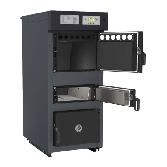
Page 45: System
10 … turbolators 4 … heating door 11 … lambda sensor 5 … cleaning door 12 … primary and sacondary air aperture 6 … exhaust take-off pipe 13 … exhaust blower 7 … gasifier room 14 … isolation © Solarbayer GmbH [210205]... -
Page 46: Re-Heating
By too slight heat consumption the risk of tar formation and overheating of the boiler is existing. The Solarbayer BioX special boiler is characterised 10.3 Cleaning of the combustion by its long combustion duration. It does not have to chamber be re-filled with fuel at frequent intervals. -
Page 47: Cleaning The Flue Pipe
The filling shaft walls are not heating surfaces and must therefore not be cleaned. The deposit arising For reasons of fire protection and according to the on the filling shaft walls is a normal chemical valid regulations: Only designated and permitted. © Solarbayer GmbH [210205]... -
Page 48: Cleaning The Exhaust Blower And The Exhaust Stack
8) Check the seals of the blower motor 9) After cleaning, reinstall the blower and reconnect the exhaust pipe to the induced draft blower 10) Make sure that the exhaust pipe to the chimney is tight © Solarbayer GmbH [210205]... -
Page 49: Lambda Sensor Cleaning
Carefully reinsert the sensor and screw it in place Reconnect the lambda sensor to the control board Mount the boiler covers again IMPORTANT! DO NOT install or remove with pliers! Damage caused by incorrect handling will not be refunded! © Solarbayer GmbH [210205]... -
Page 50: Service Plan
Use cleaning lever / automatic heat exchanger cleaning (WTR) becomes active (optional) Combustion & ash chamber Clean [(light-) grey dust black sticky coating bad combustion!] Cyclone combustion chamber Check for damage and wear Check the continuity of the flow channels © Solarbayer GmbH [210205]... - Page 51 Check doors and heat exchanger cover for tightness Heating expansion vessel Check [Inlet pressure: Gas overpressure behind the membrane of the expansion tank, if the expansion tank is depressurized on the water side; System pressure: Water overpressure of the cold system] © Solarbayer GmbH [210205]...
- Page 52 3 bar] Seals, sensors, fireclay parts and parts in contact with fire are wear parts. © Solarbayer GmbH [210205]...
-
Page 53: Boiler Status
Ready maximal boiler temperature (BOILER MAX(P02)) has been reached due to too low heat capturing. Therefore the boiler has been switched off. The boiler starts up again if the boiler temperature falls 3°C below BOILER MAX(P02). © Solarbayer GmbH [210205]... -
Page 54: Exhaust Gas Temperature Control
BOILERMAX To make it easier to understand, a normal operating sequence of the BioX wood gasifier is shown and divided into the individual control phases. Exhaust temp. (°C) Exhaust temp., soll+15K Exhaust temp., soll Time (h) © Solarbayer GmbH [210205]... -
Page 55: Residual Heat Utilisation
< 60 °C Hydraulics: Hydraulics: kleiner Kreislauf kleiner Kreislauf Buffer tank bottom: Buffer tank bottom: BioX BioX ≤ Boiler IST-Temp >≤ Boiler IST-Temp Boiler status: Boiler status: Pump status: Pumpenstatus: Mixer status: Mixer status: CLOSE CLOSE © Solarbayer GmbH [210205]... -
Page 56: Description Of Menu Navigation And Setting Values
Changes to the displayed menu / confirm change „X2“: Scroll up / increase value „X3“: Scroll down / decrease value „X4“: "ENTER" - button / Cancel change / When the " " symbol is displayed, the status changes to chimney sweep mode © Solarbayer GmbH [210205]... -
Page 57: Customer Level
RETURN MIXER CLOSE Display of the RL mixer status Sum fault / alarm Parameter menu (P) CODE: code input BOILERMAX: Temperature for control end (system goes into READY state) BOILERSOLL Temperature for control start CONTRAST SETTING © Solarbayer GmbH [210105]... -
Page 58: Specialist Level (111)
Heat exchanger cleaning(WTR) Return mixer-close* (O/X) Primary air (%) Sum error * To test the return mixer, the signals (0/X) must always be controlled in the opposite direction! Eingänge (E) Fan rotation speed WTR-monitoring Door contact -actual valve © Solarbayer GmbH [210205]... -
Page 59: Electrical Documentation
A keyboard with 5 buttons serves for the input of process data and parameters. The output takes place on a 128x64 pixel display. All interfaces and connections for controlling the burner boiler are located on the back of the control unit. They are adapted to the requirements of the boiler. © Solarbayer GmbH [210105]... - Page 60 Exhaust feedback sensor CAN bus interface Door contact sensor plug X5 plug X3 plug X2 PIN 1 PIN 1 PIN 1 PIN 1 plug X1 Heat exchanger STL-sensor cleaning (WTR) Connection X1 control board Exhaust blower © Solarbayer GmbH [210205]...
- Page 61 X3 – CAN-Bus: Interface to modules – Phönix RM 3,5 Signal Function – CAN A – CAN B – X5 – Digital input: speed feedback – Phönix RM 3,5 Signal Function +24V Supply voltage +24V DC digital input Counter input: speed feedback © Solarbayer GmbH [210105]...
- Page 62 The PTC fuse remains high-impedance as long as overload current is present. The PTC fuse thus protects continuously until the fault is eliminated or the current is switched off. When resetting itself, the resistance of the PTC fuse quickly returns to its initial value. © Solarbayer GmbH [210205]...
- Page 63 L must be removed If the STL switch-off responds, then all 230 V AC outputs of the expansion board are no longer supplied: Phase angle control: exhaust blower Relay output 230 V AC: Heat exchanger cleaning (WTR) © Solarbayer GmbH [210105]...
-
Page 64: Connection Diagram Control Board
X10 – 230 V Analog output secondary air damper – Phönix RM 3,5 Signal Function +24 V +24 V secondary air damper X11 – 230 V Analog output primary air damper – Phönix RM 3,5 Signal Function +24 V +24 V primary air damper © Solarbayer GmbH [210205]... - Page 65 Lambda sensor Plug Plug Plug Plug Plug Plug Plug Plug X5 CAN-BUS resistance = PIN 1 PIN 1 PIN 1 PIN 1 Plug X3 Plug X2 Plug X1 Return Return mixer pump © Solarbayer GmbH [210105]...
- Page 66 The PTC fuse remains high-impedance as long as overcurrent is present. The PTC fuse thus protects continuously until the fault is eliminated or the current is switched off. When resetting itself, the resistance of the PTC fuse quickly returns to its initial value. © Solarbayer GmbH [210205]...
-
Page 67: Can-Bus-Setup
The connecting lines to the analog signal sources must be wired as short as possible and without parallel routing to digital signal lines. The signal lines must be shielded. 230 V AC lines (mains line and relay outputs etc.) must not be installed parallel to analog and digital input lines. © Solarbayer GmbH [210105]... - Page 68 The signal lines should be shielded with 2 poles. Temperature measurement with thermocouples Temperature measurement with thermocouples is based on the temperature-dependent voltage that occurs at each connection of two conductors made of different metals (alloys) (Seebeck effect). © Solarbayer GmbH [210205]...
-
Page 69: Connections
Connector on the boiler Connector and connection Mains connection: L1 … Mains voltage L1 PE … Ground conductor N … Neutral line Main switch on the boiler 1 … Cable bushing 2 … Main switch 3 … Mains connection © Solarbayer GmbH [210105]... -
Page 70: Emission Measurment
enough combustion air port. Since the exhaust gas enough suitable fuel temperature for boiler control is often measured at a different enough heat transfer location, temperatures displayed vary considerably. © Solarbayer GmbH [210205]... -
Page 71: Fault Reports And Their Elimination
Buffer storage too small designed Failure 15 Lambda sensor is defective or Change the lambda sensor or F:Lambda sensor disconnected check the clamping. Failure 16: Sensor break return flow Change return flow temperature F:Return flow sensor temperature sensor © Solarbayer GmbH [210105]... - Page 72 10 page 44) Failure 27 The system has passed 1000 Acknowledge fault: F:Cleaning !!! operating hours. Boiler must be in the OFF condition (1) Press and hold the ON/OFF button (to start the boiler) © Solarbayer GmbH [210205]...
- Page 73 Too much fuel. Attention! The blower motor is defective. Service call. stopped blower leads incomplete combustion and coal tar deposits. The door contact switch is in the Service call. wrong position or defective. © Solarbayer GmbH [210105]...
- Page 74 (Note: low edge removal, surface the boiler construction: removal, crack formation etc. Service call. does not lead to any malfunction and therefore does not constitute a warranty claim.) © Solarbayer GmbH [210205]...
-
Page 75: Guarantee / Warranty (General)
Guarantee / Warranty (General) GUARANTEE / WARRANTY (GENERAL) SOLARBAYER furnaces are guaranteed for 5 years on the boiler body. In principle, we provide a 2-year warranty for the freedom from defects of movable and immovable purchase objects. Wear parts are excluded from the warranty. -
Page 76: Note
Note NOTE ------------------------------------------------------------------------------------------ ------------------------------------------------------------------------------------------ ------------------------------------------------------------------------------------------ ------------------------------------------------------------------------------------------ ------------------------------------------------------------------------------------------ ------------------------------------------------------------------------------------------ ------------------------------------------------------------------------------------------ ------------------------------------------------------------------------------------------ ------------------------------------------------------------------------------------------ ------------------------------------------------------------------------------------------ ------------------------------------------------------------------------------------------ ------------------------------------------------------------------------------------------ ------------------------------------------------------------------------------------------ ------------------------------------------------------------------------------------------ ------------------------------------------------------------------------------------------ ------------------------------------------------------------------------------------------ ------------------------------------------------------------------------------------------ ------------------------------------------------------------------------------------------ © Solarbayer GmbH [210205]... - Page 77 Note ------------------------------------------------------------------------------------------ ------------------------------------------------------------------------------------------ ------------------------------------------------------------------------------------------ ------------------------------------------------------------------------------------------ ------------------------------------------------------------------------------------------ ------------------------------------------------------------------------------------------ ------------------------------------------------------------------------------------------ ------------------------------------------------------------------------------------------ ------------------------------------------------------------------------------------------ ------------------------------------------------------------------------------------------ ------------------------------------------------------------------------------------------ ------------------------------------------------------------------------------------------ ------------------------------------------------------------------------------------------ ------------------------------------------------------------------------------------------ ------------------------------------------------------------------------------------------ ------------------------------------------------------------------------------------------ ------------------------------------------------------------------------------------------ ------------------------------------------------------------------------------------------ ------------------------------------------------------------------------------------------ © Solarbayer GmbH [210105]...
-
Page 78: Waste Disposal In Germany
- Your boiler has been dispensed from its obligations under the Ordinance on Waste Electrical Equipment and the Battery Ordinance and can be returned via a return and collection system available to you. © Solarbayer GmbH [210205]... -
Page 79: Eg/Eu Conformity Declaration
The installation and commissioning of the firing system must be carried out by qualified personnel authorised by Solarbayer. In the event of improper installation or use, connection to other machines or changes to the technical design, this declaration will lose its validity. - Page 80 Heat pumps This manual and the photos and graphics shown here Are subject to the copyright of SOLARBAYER GmbH. Technical changes and errors excepted. The current version of these assembly instructions on our homepage is valid. www.solarbayer.de © Solarbayer GmbH [210205]...
Need help?
Do you have a question about the BioX Series and is the answer not in the manual?
Questions and answers