Table of Contents
Advertisement
Quick Links
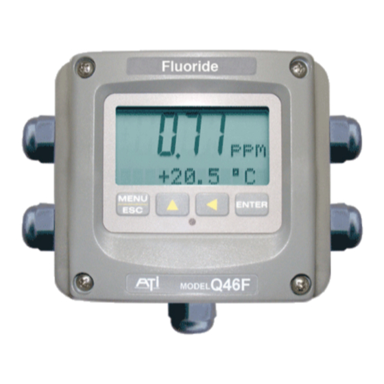
Model Q46F/82
Direct Fluoride
Home Office
Analytical Technology, Inc.
6 Iron Bridge Drive
Collegeville, PA 19426
Ph:(800) 959-0299
(610) 917-0991
Fax: (610) 917-0992
Email: sales@analyticaltechnology.com
Monitor
European Office
ATI (UK) Limited
Unit 1 & 2 Gatehead Business Park
Delph New Road, Delph
Saddleworth OL3 5DE
Ph: 0800-018-4020
+ 44 (0) 1457-873-318
Fax: + 44 (0) 1457-874-468
Email:sales@atiuk.com
Advertisement
Table of Contents

Related Manuals for Analytical Technology Q46F/82


Summary of Contents for Analytical Technology Q46F/82
- Page 1 Model Q46F/82 Direct Fluoride Monitor Home Office European Office Analytical Technology, Inc. ATI (UK) Limited 6 Iron Bridge Drive Unit 1 & 2 Gatehead Business Park Collegeville, PA 19426 Delph New Road, Delph Saddleworth OL3 5DE Ph:(800) 959-0299 Ph: 0800-018-4020...
- Page 2 PRODUCT WARRANTY Analytical Technology, Inc. (Manufacturer) warrants to the Customer that if any part(s) of the Manufacturer's products proves to be defective in materials or workmanship within the earlier of 18 months of the date of shipment or 12 months of the date of start- up, such defective parts will be repaired or replaced free of charge.
-
Page 3: Table Of Contents
PART 1 - INTRODUCTION ......... 4 PART 7 – SYSTEM MAINTENANCE ....48 General ............4 General .............48 Q46F/82 System Specifications ....6 Analyzer Maintenance ......48 Q46F/82 Performance Specifications ..7 Sensor Maintenance .........48 PART 2 – MECHANICAL INSTALLATION ..8 PART 8 –... - Page 4 Table of Figures 1 – T ............5 IGURE YPICAL LUORIDE ONITORING YSTEM 2 - Q46F E ................. 9 IGURE NCLOSURE IMENSIONS 3 - W ............... 10 IGURE ALL OR IPE MOUNT RACKET 4 - W ................11 IGURE OUNTING IAGRAM 5 - P ................
-
Page 5: Part 1 - Introduction
Part 1 - Introduction General The Q46F/82 Direct Fluoride System is an on-line monitoring system designed for the continuous measurement of fluoride ion in solution. The system is designed to measure fluoride ion directly without the use of chemical buffers and is suitable for potable water systems with stable pH and conductivity. -
Page 6: Figure 1 - Typical Fluoride Monitoring System
Q46F/82 Direct Fluoride Monitor Part 1 – Introduction Figure 1 – Typical Fluoride Monitoring System O&M Manual Rev-C (9/14) -
Page 7: Q46F/82 System Specifications
Q46F/82 Direct Fluoride Monitor Part 1 – Introduction Q46F/82 System Specifications Displayed Parameters Main input, 0.01 ppm to 2000 ppm dissolved fluoride Sensor mV Sample Temperature Loop current, 4.00 to 20.00 mA Sensor slope & zero offset Model number and software version... -
Page 8: Q46F/82 Performance Specifications
Q46F/82 Direct Fluoride Monitor Part 1 – Introduction Mounting Options Wall mount bracket standard. Panel mount adapter optional for Q46F Only Relays, Electromechanical: Three SPDT, 6 amp @ 250 VAC, 5 amp @ 24 VDC contacts. Software selection for setpoint, phase, delay, deadband, hi-lo alarm, and failsafe. -
Page 9: Part 2 - Mechanical Installation
Part 2 – Mechanical Installation General Mechanical installation of a Q46F/82 fluoride system involves mounting of the Q46F electronic assembly, mounting of the sample flowcell, and connection of sample and drain tubing. If the optional panel assembly has been supplied, the system comes assembled with flow controls to allow operators to properly adjust sample flow to a low value. -
Page 10: Wall Mount Bracket
Q46F/82 Direct Fluoride Monitor Part 2 – Mechanical Installation Figure 2 - Q46F Enclosure Dimensions Wall Mount Bracket A PVC mounting bracket with attachment screws is supplied with each transmitter (see Figure 3 for dimensions). The multi-purpose bracket is attached to the rear of the enclosure using the four flat head screws. -
Page 11: Figure 3 - Wall Or Pipe Mount Bracket
Q46F/82 Direct Fluoride Monitor Part 2 – Mechanical Installation Figure 3 - Wall or Pipe mount Bracket O&M Manual Rev-C (9/14) -
Page 12: Figure 4 - Wall Mounting Diagram
Q46F/82 Direct Fluoride Monitor Part 2 – Mechanical Installation Figure 4 - Wall Mounting Diagram Figure 5 - Pipe Mounting Diagram O&M Manual Rev-C (9/14) -
Page 13: Panel Mount, Ac Powered Monitor
Q46F/82 Direct Fluoride Monitor Part 2 – Mechanical Installation Panel Mount, AC Powered Monitor Panel mounting of the Q46F monitor uses the panel mounting flange molded into the rear section of the enclosure. Figure 6 provides dimensions for the panel cutout required for mounting. -
Page 14: Flowcell Mounting
Q46F/82 Direct Fluoride Monitor Part 2 – Mechanical Installation Flowcell Mounting The flowcell for the fluoride sensor is a sealed assembly with twist-lock connection. The sensor is inserted into the top of the flowcell by aligning the retainer pins on the sensor with the slots in the flowcell. Once inserted fully, the sensor must be rotated slightly to insure the sensor is retained if the flowcell is pressurized. -
Page 15: Fluoride Sensor
Q46F/82 Direct Fluoride Monitor Part 2 – Mechanical Installation Fluoride Sensor The fluoride sensor used in the Q46F system is a combination style electrode containing a lanthanum fluoride sensing element and a sealed silver/silver chloride reference electrode. Fluoride sensor are suitable for monitoring fluoride ion concentration in potable water systems when the source water has a very stable pH and conductivity. -
Page 16: Part 3 - Electrical Installation
Part 3 – Electrical Installation General The Q46F electronics contains a universal power supply operating on voltages between 90 and 265 VAC, 50/60 cycle. An optional version of this instrument operates from a DC power input between 12 and 24 VDC. The label on the ... -
Page 17: Figure 9 - Line Power Connection
Q46F/82 Direct Fluoride Monitor Part 3 – Electrical Installation The analog outputs from the system are present at terminals TB1. The loop-load limitation in this configuration is 500 Ohms maximum for each output. Also note that these two outputs are completely isolated from each other to insure that ground loops do not result from the connection of both outputs to the same device such as a PLC or DCS. -
Page 18: Q46F Sensor Wiring
Q46F/82 Direct Fluoride Monitor Part 3 – Electrical Installation Q46F Sensor Wiring The interconnection between the fluoride sensor and the Q46F electronics is a 4- conductor cable. The sensor cable has a coaxial cable with the center conductor and shield separated for connection to terminals 1 and 3. Two addition wires provide the temperature input and are terminated at terminals 7 and 8. -
Page 19: Relay Wiring
Q46F/82 Direct Fluoride Monitor Part 3 – Electrical Installation Relay Wiring Three SPDT relays are provided on the power supply board. None of the relay contacts are powered. The user must supply the proper power to the contacts. For applications that require the same switched operating voltage as the Q46 (115 or 230 V), power may be jumpered from the power input terminals at TB7. - Page 20 Q46F/82 Direct Fluoride Monitor Part 3 – Electrical Installation Low Power Relay Connection TB2, is used to connect to the low power 3-relay card). The Q46 provides three low power relays that can be used for switching low current DC loads. These relays are not isolated.
-
Page 21: Part 4 - Configuration
Part 4 – Configuration User Interface The user interface for the Q46 Series instrument consists of a custom display and a membrane keypad. All functions are accessed from this user interface (no internal jumpers, pots, etc.). RELAY 4-DIGIT INDICATOR MAIN DISPLAY MENU ICONS MENU ICONS SIGN... -
Page 22: 4.11 Keys
Q46F/82 Direct Fluoride Monitor Part 4 – Configuration 4.11 Keys All user configurations occur through the use of four membrane keys. These keys are used as follows: MENU/ESC To scroll through the menu section headers or to escape from anywhere in software. The escape sequence allows the user to back out of any changes in a logical manner. - Page 23 Q46F/82 Direct Fluoride Monitor Part 4 – Configuration Lower Line During normal operation, the lower line of the display indicates user-selected secondary measurements that the system is making. This also includes calibration data from the last calibration sequence and the transmitter model number and software version.
-
Page 24: Software
Q46F/82 Direct Fluoride Monitor Part 4 – Configuration Relay Area A/B The relay area contains two icons that indicate the state of the system relays (if the relay card is installed). Software The software of the Q46F is organized in an easy to follow menu-based system. - Page 25 Q46F/82 Direct Fluoride Monitor Part 4 – Configuration Any data that may be changed will be flashing. This flashing indicates user entry mode and is initiated by pressing the ENTER key. The UP arrow key will increase a flashing digit from 0 to 9. The LEFT arrow key moves the flashing digit from right to left.
-
Page 26: Figure 13 - Software Map
Q46F/82 Direct Fluoride Monitor Part 4 – Configuration Start MENU ME NU ME NU MENU ME NU ME NU MEASURE CONFIG CONTROL DIAG SECTIONS E SC E SC E SC (display only) E NTE R E NTE R ENTER ENTER... -
Page 27: Measure Menu [Measure]
Q46F/82 Direct Fluoride Monitor Part 4 – Configuration 4.22 Measure Menu [MEASURE] The default menu for the system is the display-only menu MEASURE. This menu is a display-only measurement menu, and has no changeable list items. When left alone, the instrument will automatically return to this menu after approximately 30 minutes. -
Page 28: Calibration Menu [Cal]
Q46F/82 Direct Fluoride Monitor Part 4 – Configuration Q46F VX.XX Transmitter software version number. Note: A display test (all segments ON) can be actuated by pressing and holding the ENTER key while viewing the model/version number on the lower line of the display. -
Page 29: Configuration Menu [Config]
Q46F/82 Direct Fluoride Monitor Part 4 – Configuration 4.24 Configuration Menu [CONFIG] The Configuration Menu contains all of the general user settings: Entry Lock This function allows the user to lock out unauthorized tampering with instrument settings. All settings may be viewed while the instrument is locked, but they cannot be modified. - Page 30 Q46F/82 Direct Fluoride Monitor Part 4 – Configuration Zero Filter This function forces the reading to zero when reading is below the entered value. For example, if the entered value were 0.0020 the display at 0-0019 would indicate 0.000. This feature is useful in blanking out zero noise.
- Page 31 Q46F/82 Direct Fluoride Monitor Part 4 – Configuration Iout#1 Mode This function sets analog output #1 to either track fluoride (default) or enables the PID controller to operate on the fluoride input. Press ENTER to initiate user entry mode, and the entire value will flash.
-
Page 32: Control Menu [Control]
Q46F/82 Direct Fluoride Monitor Part 4 – Configuration FAIL icon to be displayed on the LCD. Note that the Relay C indicator shows up only on the lower screen of the display next to the temperature reading. This is because the default setting for relay C is the FAIL setting. - Page 33 Q46F/82 Direct Fluoride Monitor Part 4 – Configuration If the 0% point is lower than the 100% point, then the controller action will be “reverse” acting. That is, the output of the controller will increase if the measured value is less than the setpoint, and the output will decrease if the measured value is larger than the setpoint.
- Page 34 Q46F/82 Direct Fluoride Monitor Part 4 – Configuration *Set 4 mA #2 *Set 20 mA #2 [Temp / PPM] These functions set the second 4 mA and 20 mA current loop output points for the transmitter. The default setting for this output is temperature, but it may be set for PPM if preferred.
-
Page 35: Figure 14 - Control Relay Example
Q46F/82 Direct Fluoride Monitor Part 4 – Configuration *A Phasing This function establishes the direction of the relay trip. When phase is HI, the relay operates in a direct mode. Therefore, the relay energizes and the LCD indicator illuminates when the value exceeds the setpoint. When the phase is LO, the relay energizes and the LCD indicator illuminates when the fluoride level drops below the setpoint. -
Page 36: Figure 15 - Alarm Relay Example
Q46F/82 Direct Fluoride Monitor Part 4 – Configuration Figure 16 is a visual description of a typical alarm relay application. When value rises to ≥ 1.000 ppm, relay When value falls to < 1.000 ppm, relay closes, until value falls back to < 0.950 ppm. -
Page 37: Diagnostics Menu [Diag]
Q46F/82 Direct Fluoride Monitor Part 4 – Configuration 4.26 Diagnostics Menu [DIAG] The diagnostics menu contains all of the user settings that are specific to the system diagnostic functions, as well as functions that aid in troubleshooting application problems. Set Hold... - Page 38 Q46F/82 Direct Fluoride Monitor Part 4 – Configuration The exception to this rule is the calibration failure. When a calibration fails, no corrupt data is stored. Therefore, the system continues to function normally on the data that was present before the calibration was attempted.
- Page 39 Q46F/82 Direct Fluoride Monitor Part 4 – Configuration Fail Out #1 This function enables the user to define a specified value that the main current output will go to under fault conditions. When the Relay Option Board is installed, the display will read Fail Out #1.
- Page 40 Q46F/82 Direct Fluoride Monitor Part 4 – Configuration *Failsafe This function allows the user to set the optional system relays to a failsafe condition. In a failsafe condition, the relay logic is reversed so that the relay is electrically energized in a normal operating state.
-
Page 41: Part 5 - Calibration
Part 5 – Calibration Calibration Calibration of a fluoride analyzer requires the use of two standards with about 1 decade (10X) concentration difference. For many applications, values of 1 and 10 PPM are used. However, high range applications may require the use of 10 and 100 PPM or other values depending on the application. -
Page 42: 5.12 Single Point Calibration
Q46F/82 Direct Fluoride Monitor Part 5 – Calibration 1. To start, place the fluoride sensor into the container of Solution 2 (1 PPM Standard). Allow the sensor to stabilize for a few minutes. 2. Press the Menu key once to access the Cal. Menu. Press the UP arrow to display “Cal Fluor”. -
Page 43: Temperature Calibration
Q46F/82 Direct Fluoride Monitor Part 5 – Calibration 2. Press the Menu key to go to the “Cal Fluor” display and then press Enter. 3. When the “2-point” prompt appears, press the UP key to change to 1-point and then press Enter. The monitor will prompt you for your reference solution. Press Enter. -
Page 44: Part 6 - Pid Controller Details
Part 6 – PID Controller Details PID Description PID control, like many other control schemes, are used in chemical control to improve the efficiency of chemical addition or control. By properly tuning the control loop that controls chemical addition, only the amount of chemical that is truly required is added to the system, saving money. - Page 45 Q46F/82 Direct Fluoride Monitor Part 6 – PID Controller Details é ù ò output ê ë ú û Where: Output = controller output proportional gain integral gain derivative gain time e(t) = controller error (e=measured variable – setpoint) Figure 17 - Q46 ISA PID Equation The most notable feature of the algorithm is the fact the proportional gain term affects all components directly (unlike some other algorithms - like the “series”...
- Page 46 Q46F/82 Direct Fluoride Monitor Part 6 – PID Controller Details Integral gain. Integral gain is what allows the controller to eventually drive the input error to zero – providing accuracy to the control loop. It must be used to affect the accuracy in the servo action of the controller. Like proportional gain, increasing integral gain results in the control action happening quicker.
-
Page 47: Classical Pid Tuning
Q46F/82 Direct Fluoride Monitor Part 6 – PID Controller Details Classical PID Tuning Unlike many high speed position applications where PID loops are commonly used, the chemical feed application employed by this instrument does not require intense mathematical exercise to determine tuning parameters for the PID. In fact, the risk of instability is far greater with overly tuned PID control schemes. -
Page 48: Common Pid Pitfalls
Q46F/82 Direct Fluoride Monitor Part 6 – PID Controller Details Common PID Pitfalls The most common problem occurring in PID control applications involves the false belief that proper settings on only the PID controller can balance any process to an efficient level. -
Page 49: Part 7 - System Maintenance
Part 7 – System Maintenance General The Q46F/82 Fluoride System requires minimal maintenance for reliable operation. Keep in mind that preventive maintenance on a regular schedule is much less troublesome than emergency maintenance that always seems to come at the wrong time. -
Page 50: Part 8 - Troubleshooting
Part 8 – Troubleshooting General The information included in this section is intended to be used in an attempt to quickly resolve an operational problem with the system. During any troubleshooting process, it will save the most time if the operator can first determine if the problem is related to the analyzer, sensor, or some external source. -
Page 51: Analyzer Tests
Q46F/82 Direct Fluoride Monitor Part 8 Troubleshooting 7. On systems where relays are in use, check the relay load to verify the load is within the contact rating of the relays. Relay contacts which have been used for higher power AC current loads may become unsuitable for very low signal DC loads later on because a small amount of pitting can form on the contacts. -
Page 52: Display Messages
Q46F/82 Direct Fluoride Monitor Part 8 Troubleshooting Display Messages The Q46 Series instruments provide a number of diagnostic messages which indicate problems during normal operation and calibration. These messages appear as prompts on the secondary line of the display or as items on the Fault List. -
Page 53: Spare Parts
Spare Parts Part No. Description Q46 Electronic Assembly 03-0430 Q46F front lid assembly 07-0365 100-240 VAC monitor electronics assembly 07-0367 100-240 VAC monitor electronics assembly with Profibus 01-0306 Power supply circuit board assembly 23-0018 Fuse, 100mA, 250V, (VAC units) 23-0026 Fuse, 500mA, 250V, (VDC units) 38-0072 Terminal block plug, 3 position (relays)
Need help?
Do you have a question about the Q46F/82 and is the answer not in the manual?
Questions and answers