Advertisement
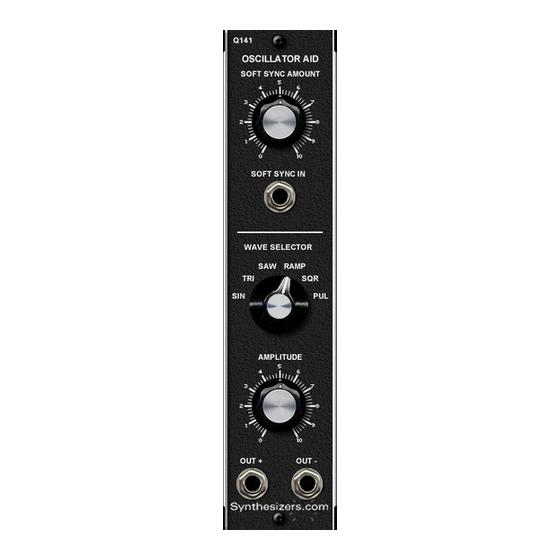
Q141
Oscillator Aid
The Q141 Oscillator Aid is designed to add functionality to the Q106 Oscilla-
tor. A soft sync input and control allows multiple oscillators to track together
with a smoother result than that provided by hard sync. A 6 position rotary
switch allows quick selection of waveforms and adds a square wave (50%
duty cycle pulse wave). An amplitude control allows the output levels to be
adjusted. The selected waveform is available in both positive and negative
polarity which can be useful when the oscillator is used as a modulation
source for filters, amplifiers and other modules. Mount the Q141 Aid on the
right or left side of the Q106 Oscillator. Wires from the Q141 attach to the
Q106 circuit board.
Specifications
Panel Size: Single width 2.125"w x 8.75"h.
Power: None.
Controls and Connectors
Soft Sync Amount Control
Sets the level of the incoming sync waveform. Adjust this control
to vary the amount of affect the signal has.
Soft Sync Input
Apply a signal here from another oscillator to cause the two oscillators
to sync together. Normally this is a triangle or sine wave.
Wave Selector Switch
Allows quick changes in the waveform present at the 2 output
Connectors.
+Output Connector
This is the wave in its non-inverted form.
-Output Connector
This is the wave in its inverted form.
Aug 2014
Advertisement
Table of Contents

Subscribe to Our Youtube Channel
Summary of Contents for Synthesizers.com Q141
- Page 1 Mount the Q141 Aid on the right or left side of the Q106 Oscillator. Wires from the Q141 attach to the Q106 circuit board.
- Page 2 Q141 Oscillator Aid Aug 2014 Amount of Soft Sync Soft Sync Section Use a waveform from another oscillator to Sync oscillators together Select a waveform from the Oscillator Waveform Section Controls the amplitude of the waveform Output of the selected waveform.
- Page 3 Testing No calibration is required on this module. 1. Connect the cables from the Q141 to the Q106 oscillator per the PCB drawing. 2. View the waveforms present at the +OUTPUT and –OUTPUT connectors while switching the Waveform selector switch, and while adjusting the output level.
Need help?
Do you have a question about the Q141 and is the answer not in the manual?
Questions and answers