
Summary of Contents for TE Connectivity EAZY-CAL LVC-4500
- Page 1 EAZY-CAL™ LVC-4500 LVDT Diff/Sum Mode Signal Conditioner User Manual Manual P/N 0653 0008 0000 Rev. -- April 18, 2016 TE CONNECTIVITY SENSORS /// LVC-4500 USER MANUAL 07/2019 Page 1...
-
Page 2: Table Of Contents
Error! Bookmark not defined. RS-485 DIGITAL INTERFACE Command Format Commands Command Table SYNCHRONIZATION ERROR! BOOKMARK NOT DEFINED. ERROR! BOOKMARK NOT DEFINED. ERROR DETECTION AND INDICATION LVC-4500 GENERAL SPECIFICICATIONS ERROR! BOOKMARK NOT DEFINED. TE CONNECTIVITY SENSORS /// LVC-4500 USER MANUAL 07/2019 Page 2... -
Page 3: General Description
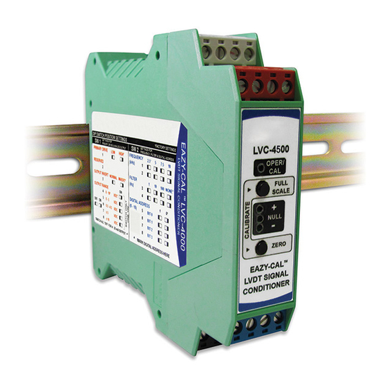
Once the newly replaced LVC-4500 is in position the terminal plugs are then pushed back into their matching color coded positions by hand. The following sections describe the features and operation of the LVC-4500. TE CONNECTIVITY SENSORS /// LVC-4500 USER MANUAL 07/2019... -
Page 4: Electrical Connections
Diag a LVDT/LVRT Co e tio Diag a Select either current or voltage output using DIP SW1. Notes: Secondary Center Tap connection is required only in Diff/Sum Mode. TE CONNECTIVITY SENSORS /// LVC-4500 USER MANUAL 07/2019 Page 4... -
Page 5: Dip Switches
To access the DIP switches, the back cover is removed from the enclosure. Use a screwdriver or similar tool to depress the top latch. The cover will spring forward. Repeat with the bottom latch, then gently pull the PCB out, as shown: TE CONNECTIVITY SENSORS /// LVC-4500 USER MANUAL... - Page 6 ON ON ON ON ON ON ON ON ON ON ON ON ON ON ON ON ON ON ON ON ON ON ON ON ON ON ON ON ON ON ON ON (ADDR5) TE CONNECTIVITY SENSORS /// LVC-4500 USER MANUAL 07/2019 Page 6...
-
Page 7: Front Panel
Cali atio Mode Du i g Cali atio : P ess )E‘O utto to set o e i i u e dpoi t positio TE CONNECTIVITY SENSORS /// LVC-4500 USER MANUAL 07/2019 Page 7... -
Page 8: Calibration Procedure
PC with a USB-to-RS485 adapter attached. A terminal program (Hyperlink) or 3rd party software is required. Port parameters are set to 9600 bps, no parity, 8 data bits and 1 stop bit (9600, NP, 8,1). Data is ASCII. TE CONNECTIVITY SENSORS /// LVC-4500 USER MANUAL... - Page 9 PC. All actions for a calibration procedure should be performed either by way of manually pushing the front panel buttons or by way of entering commands on a PC using the RS-485 communication link. It should not involve procedural steps that mix both approaches. TE CONNECTIVITY SENSORS /// LVC-4500 USER MANUAL...
- Page 10 A o t the ali atio p o edu e. :aa a o tCal C‘ CAL ABO‘T getS ‘etu s the s h o izatio state. :aa getS C‘ MASTE‘ / SLAVE / LISTEN TE CONNECTIVITY SENSORS /// LVC-4500 USER MANUAL 07/2019 Page 10...
- Page 11 VDC or 0-5 VDC ranges, the error voltage is -0.5 VDC and -0.25 VDC respectively. For 4-20 mADC range, the error current is 0 mADC. RS-485 Bus: The getError command returns the error status. TE CONNECTIVITY SENSORS /// LVC-4500 USER MANUAL 07/2019 Page 11...
- Page 12 P i a o Se o da Wi e B eak Dete t, i di ated LED, E o Flag, a d E o Output Le el E o Flag olle to output, V DC a . TE CONNECTIVITY SENSORS /// LVC-4500 USER MANUAL 07/2019 Page 12...
- Page 13 TE Connectivity‘s obligations shall only be as set forth in TE Connectivity‘s Standard Terms and Conditions of Sale for this product and in no case will TE Connectivity be liable for any incidental, indirect or consequential damages arising out of the sale, resale, use or misuse of the product.
Need help?
Do you have a question about the EAZY-CAL LVC-4500 and is the answer not in the manual?
Questions and answers