Advertisement
Quick Links
- Electronic Limit
Switches
- Very Accurate
- Easy to use
- Robust
- Dependable
- High Resolution
- Non Contact
Measurement
- Wide Temp.
Range
EPS 02 Operating Instructions
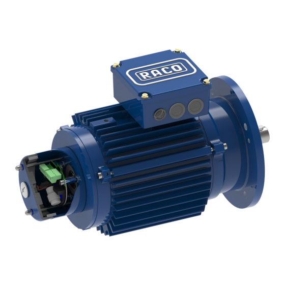
RACO Electronic Position Sensor
Introduction
The RACO electronic positioning system
EPS 02 has been especially designed for end
of stroke limit switch detection in electro-
mechanical linear actuators. The operating
principal is based on a non contact coupling
through a magnetic field. It detects angular
movement of the rotating motor shaft or
actuator screw in relationship to the
stationary sensor on the printed circuit board
and converts this signal into an absolute
linear position signal.
The
position sensor
EPS
integrated
the
housing
mounted at the
opposite side of
the motor drive shaft.
If the actuator is
equipped
with
additional
auxiliary
equipment
like
hand wheel, etc..
the
electronic
position
sensor
will be mounted in
the lateral accessory housing "D" located at
the coupling housing connecting the actuator
screw with the drive motor.
In the EPS 02 the two end of stroke limits
can be set via on board push buttons and / or
the TTL level communication interface. In
addition an optional external reference limit
switch can be used. Three on board LED's
will guide the user through the initial setup
procedure and will function thereafter as
operation control signals.
Function
The EPS 02 consists of two potential
free relay contacts, an input channel for
the motor over-temperature switch, and
the optional external reference limit
switch.
Motor Over-Temperature Switch
To protect the RACO actuator motor
from overheating, for example from
electronic
frequent starts and stops or excessive
overloading of the actuator, the opening
02
is
of the motor thermal switch will be
typically
monitored. If the motor thermal switch
into
is wired into terminals X1 pin 4 and pin
actuators
5, both limit switch relay contacts will
accessory
open up in the event of an over
"A"
temperature. The red LED will blink on
and off to indicate that condition.
External Reference Switch
An optional external reference switch
can be used to indicate the retracted
position. The external device has to be a
normally open limit switch or a PNP
proximity switch. The switch will be
connected between terminal X1 pin 3
and pin 4. In the mode external
reference switch, the actuator will
retract until the external switch is made.
With the rising voltage edge at the input
X1 Pin 3 the internal EPS 02 position
reference point will be set to zero each
time. The extended stroke limit position
is defined by the stored stroke length
and the above described zero position.
Make sure that the external reference
switch is positioned in front of the
Advertisement

Summary of Contents for Raco EPS 02
- Page 1 With the rising voltage edge at the input In the EPS 02 the two end of stroke limits X1 Pin 3 the internal EPS 02 position - Wide Temp.
- Page 2 Connection Technical Data The EPS 02 is equipped with a four pole EPS 02 Power Supply requirement: pluggable X2 connector for the limit switch Voltage: 24V DC output relay contacts and a five pole...
- Page 3 Adjustment retracted position: Manual Setup Procedure Note for units with external limit switch: The EPS 02 limit switch function can be As mentioned before, do not make any configured via the two onboard push buttons. adjustments in mode 1 if the unit is This is only necessary during startup or configured for an external limit switch.
- Page 4 TTL to USB can be Hold down the push button S1 for 0.5 to 1 used. The 10 pin square post connector RACO TTL to RS232 Signal Converter second. The LED pattern will change to its as well as the 4 pole plug connector normal operational condition.
- Page 5 This value represents the number of rotations stored in the battery backed up RAM. Stroke length of Actuator at the EPS 02 sensor head to account for the The factory set zero position represents Relationship of Stroke length full nominal stroke of the actuator.
- Page 6 The slide bar output and numerical value is updated immediately as the sensor changes its rotational position. EPS 02 mounted behind motor brake with extended shaft in submersible housing External EPS 02 setup via IP68 plugable TTL to USB connection cable...
- Page 7 Digital Output Configuration Screen: Display Functions: Absolute Position Digital output configuration: The screen channels on customers PLC control On / Off selection of Outputs provides an easy selection of assigning equipment. Limit Positions stroke limit switching points over the entire Impulses per Revolution of Square stroke length of the actuator.
- Page 8 Analog Output Configuration Screen (EPS06 only): Display Functions: Absolute Position Selected Analog signal Scaling of Analog Signal Analog Output Function: With the pull down menu “Analog Output Function” the following selections can be made: 0-10V, 10-0V, 0-20mA, 20-0mA, 4-20mA and 20- 4mA.
- Page 9 Thrust Overload Screen (EPS06 only): Display Functions: Speed Sensor Function Enabled or Disabled Shut off RPM Setting Startup Delay Time Forward Thrust Overload Function: The thrust supervised until the reversing motor Startup Delay Time Reverse overload function screen enables and starter is turned off.
- Page 10 Installation and Help in Case of Connection Problem Trouble Connection Problems Shooting The latest version of the RACO Tools setup The most common problem is the software can be downloaded from the incorrect selection of the COM Port. RACO website www.racointernational.com...
-
Page 11: Wiring Diagram
Wiring Diagram Examples The EPS 02 limit switch contacts are hard wired into the reversing motor starter circuit. The EPS 02 output signals are wired as permissive signals into the control circuit of a variable frequency drive.
Need help?
Do you have a question about the EPS 02 and is the answer not in the manual?
Questions and answers