Table of Contents
Advertisement
Quick Links
Advertisement
Table of Contents

Summary of Contents for MEL M70LL Series
- Page 1 MIKROELEKTRONIK GMBH Intelligente Sensoren & Mess-Systeme M7LL / M70LL Laser-Sensors with integrated Ethernet Interface Manual MEL Mikroelektronik GmbH Breslauer Str. 2 D‐85386 Eching Tel. +49 89 / 327 150‐0 Fax +49 89 / 319 20 23 www.MELsensor.de © Copyright MEL Mikroelektronik GmbH ...
-
Page 2: Table Of Contents
Sensor head......................................12 Electronic unit ...................................... 12 RS‐232 Debug interface ..................................13 Communication between electronic unit and PC ..........................13 Tasks of the integrated Microcontroller............................... 13 Tasks of the PC‐Software..................................13 Communication components ................................13 Set up of IP Address of the sensor................................ 13 Solve IP address conflicts..................................14 Elements of the IP default settings..............................14 Operating conditions for the sensor..............................14 HB‐M7LL‐M70LL‐E.doc page 2 of 23 V20130301 MEL Mikroelektronik GmbH, Breslauer Str. 2, 85386 Eching / Germany www.MELSensor.com ... -
Page 3: Hints For Hardware And Firmware Versions
After a reset the sensor automatically restarts. Settings were not reset. Factory default parameters could change without notice tot he given documentation. Relevant is always the actual interface description of MEL. For details contact MEL technical support or MEL sales team. Technical data is not included in this manual. Technical data is given in the MEL data sheet(s) of the product. Data sheets may be changed without notice in this manual. In this manual all hardware connections, interface definitions and software registers are documented. While the Ethernet data ... -
Page 4: System Description
Threshold Min / Max adjustable (in software) Error output Option thickness measurement Check dimensions Position detection of small parts Position detection on conveyor belt Detection of tool position in stamping machines Detecion of sheet duplication Position / break detection in tooling machines Robot arm position Presence detection Bore hole depth Fill level detection Vibration analysis Crashtest recording Suspension testing Software for sensor system M7LL with Ethernet interface and connection cables to PC are available on request. HB‐M7LL‐M70LL‐E.doc page 4 of 23 V20130301 MEL Mikroelektronik GmbH, Breslauer Str. 2, 85386 Eching / Germany www.MELSensor.com ... -
Page 5: Function Principle
Factory default setting of the Min / OK / Max LED’s is at the boundary of the measurement range. When OK is lit, the object is in range. FALSCH Hint: The sensor should be mounted with plastic washers. This helps to avoid electromagnetic interference Montagerichtung problems. If moving or striped objects need to be captured, the sensor head is to be mounted at 90° to the movement axis, as shown in the picture at the right side. RICHTIG HB‐M7LL‐M70LL‐E.doc page 5 of 23 V20130301 MEL Mikroelektronik GmbH, Breslauer Str. 2, 85386 Eching / Germany www.MELSensor.com ... -
Page 6: Thickness Measurement
The maximum of the intensity is not in the center of the spot. maximum of the intensity is not in the center of the spot. In direction A, the error is minimal; in direction B it is maximal. In direction A, the error is minimal; in direction B it is maximal. 15° The sensors are equipped with a automatic intensity regulation The sensors are equipped with a automatic intensity regulation Drehachse for matching to more or less reflecting objects. When the for matching to more or less reflecting objects. When the 30° surface is changing during measurement, the intensity is kept surface is changing during measurement, the intensity is kept Objektoberfläche constant by the regulation system. constant by the regulation system. Drehachse The measurement has a small dependency from inclination The measurement has a small dependency from inclination angle. Rotation on axis A up to 30° and rotation on axis B up to angle. Rotation on axis A up to 30° and rotation on axis B up to 15° do not cause big measurement error. Measurements on a surface with good diffuse reflection are less depending on angle than 15° do not cause big measurement error. Measurements on a surface with good diffuse reflection are less depending on angle than measurements on mirroring surfaces. (See the picture above). measurements on mirroring surfaces. (See the picture above). The measurement error shows up as a change in the ratio of output voltage / distance. When the error is constant, a special The measurement error shows up as a change in the ratio of output voltage / distance. When the error is constant, a special calibration could eliminate the error. calibration could eliminate the error. HB‐M7LL‐M70LL‐E.doc page 6 of 23 V20130301 MEL Mikroelektronik GmbH, Breslauer Str. 2, 85386 Eching / Germany www.MELSensor.com ... -
Page 7: Ambient Light
The absolute error is the deviation from the calculated distance. It is shown in a table on the right side of the report. The sensing element (PSD) does not give results which are in a linear relation to the distance. Therefore the electronic system linearises the output signal. The linearization compensates different surface reflectivity and creates a output voltage proportional to the distance. Reaction time at analog outputs is extremely fast with laser sensors. It is specified to be less than 50 μsec for the M7LL or 5 μsec for the M70LL (rise from 0 to 90% of final value). With DIP‐switches in the electronic unit the integration time can be set higher. This reduces noise and improves accuracy. Please find details on page Fehler! Textmarke nicht definiert.. The electronic unit has two ouputs with adjustable thresholds for minimum and maximum. The thresholds can be set with the MEL demo software for M7LL over the whole range of the sensor. In order to avoid oscillations, the thresholds have a small hysteresis. When the Min threshold is hit, the Min output goes high. When Min or Max outputs are activated, OK signal goes off (low). When OK is active, neither Min nor Max could be active. The thresholds are only active when the object is inside range. For easy of first use, the thresholds are factory default set to the range limits. The thresholds are sampled with the internal CPU processing clock rate of 30 kHz; this is equal to a reaction time of 0.03 msec. Other than mechanical systems the optical sensors do not have a hysteresis or problems with repeatability. Accuracy is limited by surface condition and system noise. HB‐M7LL‐M70LL‐E.doc ... -
Page 8: Connections
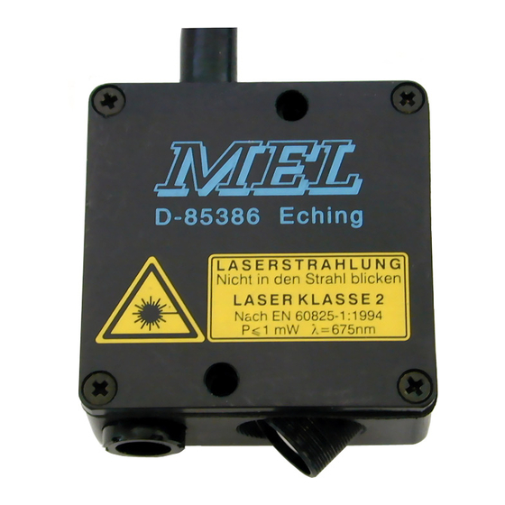
Tipp: configure the IP address of your sensor before you add a M7LL‐ / M70LL‐ sensor to your network. Use a Web browser for set up of the IP address, see page 17 for details. The picture on the right side shows the sensor head M7LL/4. The sensor models, options and accessories are listed in the M7LL‐ and M70LL‐sensor families datasheets. Tipp: the M7LL / M70LL data sheets can be downloaded from the MEL website http://www.melsensor.de or send an E‐mail to: info@melsensor.de. High temperature Ethernet and control cables are available on request! Standard Sensor models send out red laser light less than 1 mW of optical power. They are laser safety class 2. Depending on the model, special sensors might have laser safety class 3R, providing higher optical output of up to 5 mW. ... -
Page 9: Connector Specification D-Sub-25
This is the best way to connections to avoid ground loops. This is the best way to connect potential free inputs. connect potential free inputs. HB‐M7LL‐M70LL‐E.doc page 9 of 23 V20130301 MEL Mikroelektronik GmbH, Breslauer Str. 2, 85386 Eching / Germany www.MELSensor.com ... -
Page 10: Electronic Unit
Blau + Weiß unused + 6 Receive data ‐ Red 6 Green Transmit data ‐ 7 unused + Brown+ White 7 Brown+ White unused + 8 unused ‐ Brown 8 Brown unused ‐ Picture below: crossed Ethernet cable Tipp: a direct connection between sensor and network card requires a crossed Ethernet cable. The picture on the left side shows up the position of the blue and red colored wires clearly. When a Ethernet switch is in use, a cross over cable may not be necessary, as the switch may control and correct position of the signals by auto MDI / auto sense function. HB‐M7LL‐M70LL‐E.doc page 10 of 23 V20130301 MEL Mikroelektronik GmbH, Breslauer Str. 2, 85386 Eching / Germany www.MELSensor.com ... -
Page 11: Technical Data M7Ll
1.000 Hz 6 mV 3.0 µm 1.000 Hz 100 mV 50 µm 250 Hz 3 mV 1.5 µm 250 Hz 60 mV 30 µm 1000Hz 2 mV 1.0 µm 1000Hz 40 mV 20 µm 25 Hz 1.5 mV 0.7 µm 25 Hz 20 mV 10 µm 20 Hz 1 mV 0.5 µm 20 Hz 15 mV 7.5 µm *** measured at the analog output; ± 10 V = 10 mm HB‐M7LL‐M70LL‐E.doc page 11 of 23 V20130301 MEL Mikroelektronik GmbH, Breslauer Str. 2, 85386 Eching / Germany www.MELSensor.com ... -
Page 12: Technical Data M70Ll
0.5 µm 250 Hz 4 mV 0.10 µm 230 Hz 2 mV 0.4 µm 230 Hz 4 mV 0.10 µm Weight and dimensions please see individual data sheets Analog output 1 ± 10V / 10 mA Analog output 2 4…20 mA Min, Max, OK switching outputs 0 / 24 V; 5 mA HB‐M7LL‐M70LL‐E.doc page 12 of 23 V20130301 MEL Mikroelektronik GmbH, Breslauer Str. 2, 85386 Eching / Germany www.MELSensor.com ... -
Page 13: Rs-232 Debug Interface
TCP‐ Clients and ‐Server are software components in the software development environment. These are represented in the compiled application software as “ports”, using protocols, commands and data. Each sensor has its own IP address matching to the subnet mask. The settings of IP address, port and subnet mask must be set correctly when installing a new sensor. These parameters are responsible for proper function of the unit in the network. Data is stored in the sensor before sending. The IP address is stored in the sensor electronic unit. For set up of IP address a Web Browser can be used. See details on page 17. M7LL / M70LL sensors are delivered with a factory default address and with a “Working‐IP“‐Address . The sensor is connected to the network and makes a Peer‐to‐Peer connection. Once the connection is established to a certain PC, the sensor will not communicate to any other device. The sensor can be connected with a crosslink network cable directly to the PC. Gateways or special hardware is not required. The factory default address will be activated, when the s‐output is connected to the s‐input at power on. The factory default address is hard coded and can not be changed by the user. At delivery the working IP address is set to 192.168.122.245. When a different IP address has been set, a sticker will indicate the actual IP ddress. The Ip address can be set with a Web Broswer. Details are given on page 17. The sensor restarts automatic and sends a message to the Web Browser. HB‐M7LL‐M70LL‐E.doc page 13 of 23 V20130301 MEL Mikroelektronik GmbH, Breslauer Str. 2, 85386 Eching / Germany www.MELSensor.com ... -
Page 14: Solve Ip Address Conflicts
Tipp: in order to allow communications in more than one subnet, a second (third) IP address for the network adapter could be set in status | properties | advanced. Elements of the IP default settings MAC‐Adresse 00‐08‐DC‐00‐00‐00 Seriennummer MM‐YY‐ZZZ Sensor‐IP 169.254.150.161:3000 = factory default IP Addresse (S‐input and S‐output connected) Subnetz‐Maske 255.255.255.0 Gateway IP 169.254.150.1 TCP Port last segment of the TCP/IP‐Address (for example 3000) When the power is on, the sensor automatically start to send data. The TCP protocol cares about sending and receiving dta packets complete, the user must not care for this. HB‐M7LL‐M70LL‐E.doc page 14 of 23 V20130301 MEL Mikroelektronik GmbH, Breslauer Str. 2, 85386 Eching / Germany www.MELSensor.com ... -
Page 15: Data Format And Interface Description
0xFF unsigned int AD Frequenz 56 2 30000 unsigned int AD ValuesMax 58 2 200 unsigned int AD Values 60 400 2x200 Werte each 16 Bit distance unsigned int ADI Values 460 200 1x200 Werte each 16 Bit intensity unsigned char ADLValues 660 200 1x200 Werte each 16 Bit Laser control value unsigned char Gesamte Länge 860 HB‐M7LL‐M70LL‐E.doc page 15 of 23 V20130301 MEL Mikroelektronik GmbH, Breslauer Str. 2, 85386 Eching / Germany www.MELSensor.com ... -
Page 16: Rs-232 Prompt After Power On
Gateway Address Activity of Web‐Server Set up value for Max and Min ‐ Ethernet Link Status Example fo a RS‐232 Prompt: ************************************************************************************** M27‐iLAN v.0.1.2 110330 Seriennummer: 03 11 003 EthernetStack: init EthernetStack: config EthernetStack: 100MBit EthernetStack: Working Settings MAC: 00:08:DC:04:BE:DB IP: 192.168.123.201:3000 SubNetz: 255.255.255.0 GateWay: 192.168.123.1 WebServer‐Socket: aktiv Trigger‐Max: 63000 Min: 02000 TCP‐Connecting... EthernetLinkNOK disconnected disconnected EthernetLinkOK ******************** HB‐M7LL‐M70LL‐E.doc page 16 of 23 V20130301 MEL Mikroelektronik GmbH, Breslauer Str. 2, 85386 Eching / Germany www.MELSensor.com ... -
Page 17: Integrated Web-Server
Then click the send button to send the parameters to the sensor or press ENTER. after a short while the sensor sends a confirmation screen. The sensor restarts automatically and uses the new parameters. please note: when you have set a new IP address, your software must reconnect to the new IP address. * the IP‐Adresse of the PC should be resembling tot he IP address oft he sensor. Only the last 3 digits should be different. Example: Sensor –IP = 192.168.122.245 PC‐IP = 192.169.122.10 HB‐M7LL‐M70LL‐E.doc page 17 of 23 V20130301 MEL Mikroelektronik GmbH, Breslauer Str. 2, 85386 Eching / Germany www.MELSensor.com ... -
Page 18: Trouble-Shooting
Are sensor and PC in the same PC and sensor must be in the network card in the PC subnet? same network segment (subnet) Eth.‐Link and 100Mbit are lit Turn off firewall Allow communication for port Windows 7 sometimes creates but no network connection 3000, TCP protocol problems, because it deactivates network when it is not active. Arp ‐d Reset network card cache Slow connection Is the network card a 100 Use another PC, another Do not use hubs. Mbit version? Ethernet switch The connection to the PC is The PC is too slow Use a faster PC Set graphic display to working, but measurement minimum settings results are received with a delay of a few seconds HB‐M7LL‐M70LL‐E.doc page 18 of 23 V20130301 MEL Mikroelektronik GmbH, Breslauer Str. 2, 85386 Eching / Germany www.MELSensor.com ... -
Page 19: Maintenance
picture: clean Sensor please note: oily finger prints cause severe measurement errors. The same applies to water drops or other liquids. During the installation of sensors take care that no sunlight could radiate ‐ directly or reflected on a surface ‐ into the sensors receiving optics. This could cancel the function of the sensor. Water drops on the optic system or on the front make severe distortion on the measurement. Water drops work like a lens. They may cause sensors to fail permanently. Standard sensors were delivered with laser wavelength of 650 ... 670 nm. For special purpose and on request MEL will deliver other laser wavelength. The technical data for those sensors are basically the same as for 650 nm sensors. Sensors using different wavelength would not interfere into each other optical system. This allows to use two laser sensors having a laser spot near to the other sensor without interference problems. Sensors with different laser wavelength may hav different laser safety class or different technical data. HB‐M7LL‐M70LL‐E.doc page 19 of 23 V20130301 MEL Mikroelektronik GmbH, Breslauer Str. 2, 85386 Eching / Germany ... -
Page 20: Laser Safety
Before cleaning switch off laser Before cleaning switch off laser Use a piece of paper to locate the (invisible) beam Use a piece of paper to locate the (invisible) beam Never use mirrors in the environment Never use mirrors in the environment Shield the workplace Shield the workplace Use a protective cover / curtain Paint machine parts black mat No bio hazard will occur when the laser beam touches the skin. Products in laser safety class 2 have a label like the picture on the right side. These products do not require special laser safety. Sensors with laser output power higher than 1 mW and lower than 5 mW are laser safety class 3R. These products have a label according to FDA and IEEE / DIN‐ISO regulations, specifying laser class 3R, laser wavelength and laser energy. For these products, protective means as mentioned above are required. According to FDA / DIN‐ISO regulations a laser safety expert must be available in the company using such products. HB‐M7LL‐M70LL‐E.doc page 20 of 23 V20130301 MEL Mikroelektronik GmbH, Breslauer Str. 2, 85386 Eching / Germany www.MELSensor.com ... -
Page 21: Software Examples
Manual M7LL / M70LL Laser‐Sensors For integration of the M7LL‐ and M70LL‐ sensors a DLL is available. More details are available on request. Our software development engineers use Visual Studio / C++. Source code published by MEL should be considered as examples. This code could have bugs and MEL could not make warranties if this code would cause harmful damadge to your system or render it inoperable. MEL may change the code examples without notice. #define M27ILANPROTOKOL2302ETHERNETPACKETSIZE 860 #define ADVALUESPROTOKOL2302MAX 200 typedef struct { unsigned int uiVersionProtokol; //2 0x2302 unsigned int uiVersionProtokolSize; //2 860 unsigned int uiSerienNummerMJ; //2 MMJJ unsigned int uiSerienNummerCnt; //2 XXX unsigned long ulEinschaltzaehler; //4 unsigned char ucReserved[20]; //20 unsigned int uiPacketNummer; //2 fortlaufende Nummer unsigned char ucEthSpeed; //1 10/100‐MBit/s unsigned char Reserved1[3]; //3 unsigned int uiAMB; //2 AnfangsMessBereich unsigned int uiMB; //2 MessBereich unsigned int uiTriggerMaxValue; //2 im WebBrowser eingestellter Wert unsigned int uiTriggerMinValue; //2 im WebBrowser eingestellter Wert unsigned char ucTriggerMaxIntensity; //1 142 unsigned char ucTriggerMinIntensity; //1 14 unsigned int uiTriggerStatus; //2 (uiTriggerMax << 1) | uiTriggerMin unsigned int uiReserved2; //2 unsigned int uiADZMaxValue; //2 0xFFFF ... - Page 22 { sTCP = 0; bRunConnect = FALSE; TRACE("SocketError\n"); } //set TimeOut for die “recv” function setsockopt(sTCP, SOL_SOCKET, SO_RCVTIMEO, (const char*)&dwRecvTimeOut, sizeof(int)); while(bRunConnect) { //set up (initiate) connection if (connect(sTCP, (SOCKADDR*) &serv_addr, sizeof(SOCKADDR)) == INVALID_SOCKET) { //if failed keep trying to initiate connection } else { //connection established: get data bRunRead = TRUE; while(bRunRead) { dwReceived = recv(sTCP, chBuffer, TCPBUFSIZE, NULL); if ((dwReceived == 0) || (dwReceived == INVALID_SOCKET)) { //connection was probably cut, make sure //and re‐initiate the connection bRunRead = FALSE; bRunConnect = FALSE; closesocket(sTCP); } else { //here you find received data HB‐M7LL‐M70LL‐E.doc page 22 of 23 V20130301 MEL Mikroelektronik GmbH, Breslauer Str. 2, 85386 Eching / Germany www.MELSensor.com ...
- Page 23 Manual M7LL / M70LL Laser‐Sensors //number of received data is in dwReceived } } } } //release socket closesocket(sTCP); WSACleanup(); } Use the “send” function for sending data to the sensor. Like with the „recv“ function it is necessary to set up connection to the sensor before using the send fucntion. In the above example you could replace „recv“‐function with send“ function. // Data Buffer // data buffer contains the command // to set the sensor in single mode char chBuffer[2] = {0x14, 0x01}; send(sTCP, chBuffer, 2, NULL); ************************************************************************************************************ HB‐M7LL‐M70LL‐E.doc page 23 of 23 V20130301 MEL Mikroelektronik GmbH, Breslauer Str. 2, 85386 Eching / Germany www.MELSensor.com ...
Need help?
Do you have a question about the M70LL Series and is the answer not in the manual?
Questions and answers