
Summary of Contents for REGULA 4197
- Page 1 Certified Quality Management System MAGNETO-OPTICAL VISUALIZER Regula 4197 User’s Guide 2018...
-
Page 3: Table Of Contents
CONTENTS 1 FUNCTION . . . . . . . . . . . . . . . . . . . . . . . . . . . . . . . . . . . . . . 4 2 AREAS OF APPLICATION . -
Page 4: Function
Magneto-optical visualizer (hereinafter referred the «visualizer») Regula 4197 is intended for expert examination of document magnetic protection. The device visualizes images executed with magnetic inks, tapes, fibers and other magnetic materials. The visualized images are displayed on a PC monitor and can be stored as files of normal raster graphic formats. -
Page 5: Device Design
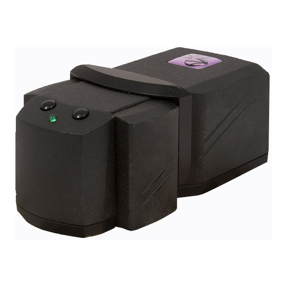
DEVICE DESIGN Visualizer Regula 4197 consists of the following components (Figure 1): an optical electronic block 1 and a magnetic excitation system 2. The right 3 and left 4 functional buttons and a LED indicator 5 are located on the top of the optical electronic block. -
Page 6: Delivery Set
User’s guide Test object DESCRIPTION OF DEVICE OPERATION The magneto-optical visualizer Regula 4197 is a USB device. Its power supply, control, output and processing of examination results are carried out with the help of a PC. The visualizer is to be connected to one of PC USB-ports. -
Page 7: Operation Order
located inside the device. After special preliminary processing, the image is output to the CADR application window. Near the sensitive element there is an inductor. In certain visualizer operation modes, it generates series of magnetic impulses affecting the sensitive element. The inductor is intended to increase sensitivity of the visualizer, improve image quality and to generate magnetic displacement fields used in the mode assessing magnetic parameters of document security features. - Page 8 PC operating system requires installation of the visualizer driver. For more details see paragraph 6.2). Visualizer software installation The software supplied with Regula 4197 visualizer includes: 1) CADR application, 2) visualizer driver. The procedure of software installation is the following: Insert the installation medium with the visualizer software into the disk drive or USB port of the PC.
-
Page 9: Operation Execution
When installation is complete, open the Device Manager window to check that a new device «Magneto-optical Visualizer 4197» has appeared in the «Forensic Devices» section. Make sure that the device is installed correctly (without «?» or «!» marks in the Device Manager panel) . - Page 10 Put the visualizer on the examined document with the sensitive element facing downwards. Not all documents are printed using magnetic ink. So if there is no document with magnetic security features at the initial startup of the device, use the test object from the visualizer delivery set to check device operation.
- Page 11 Figure 5...
-
Page 12: Background And Frame Input Options
To switch the format, select the menu item [File] -> [Videodriver] -> [Video format] (Figure 6). Figure 6 Background and frame input options The visualizer can operate in several modes that allow obtaining images of different quality. But the modes in which high-quality images are captured require more time to form a frame. - Page 13 contact with the magnetic image of the examined document. Then the program subtracts the background from the frame. As a result, in the obtained image, the user can see only the document magnetic image against a solid gray background. Such technology allows filtering possible noises, artifacts and brightness irregularities which the initial (background) image formed by the magneto-optical crystal may contain.
-
Page 14: Processing The Results
once. Afterwards, the background is subtracted from this frame. This operation mode is the most simple and quick. Discovery — a background image is input twice. Then the arithmetic mean of those two images is used as the background. It means that two brightness values of each pixel are summed up and divided by two. - Page 15 on the F button (Figure 8) located in the lower row of the toolbar. The «Deviation from middle» window will open. If the mentioned button does not appear on the toolbar when starting the CADR application for the first time, double click on the free space of the toolbar lower row with the left mouse button while holding the <Ctrl>...
- Page 16 Here is the list of image processing parameters and their purpose: Width of the dead zone — specifies the range of the pixel brightness deviation from the average value. Within this range, brightness values are adjusted to the average value. Shift of the dead zone —...
- Page 17 Assessment of magnetic parameters The «Magnetic measurements» function of the CADR software is intended for assessing magnetic parameters of the materials used to produce document security features and for comparing these parameters in examined documents and in templates (certainly authentic documents) for a further conclusion about a probable forgery.
- Page 18 To call the «Magnetic measurements» function, left-click on the E button (Figure 9a) or left-click in the menu [Modules] -> [«MagMouse / Regula 4197»] -> [Magnetic measurements] (Figure 9b). Before running the «Magnetic measurements» function, input a background image as described in paragraph 6.3 (Button A, Figure 7).
- Page 19 Figure 9a Figure 9b...
- Page 20 30 s while the measurements are taken. Then left-click on the E button (Figure 9a) or in the menu [Modules] ->[«MagMouse / Regula 4197»] -> [Magnetic measurements] to call the «Magnetic Measurements» function (Figure 9b). As the «Magnetic Measurements» function starts, two windows open.
- Page 21 Figure 9d ATTENTION! TO ACHIEVE ACCURATE COMPARATIVE ASSESSMENT OF MAGNETIC PARAMETERS, MAKE SURE THE CONTROL AREAS OF EXAMINED AND REFERENCE DOCUMENTS COINCIDE . WHEN CHOOSING THE CONTROL AREA, THE AREAS WITH HIGHER PRINT DENSITY AND THICKER INK LAYER ARE PREFERABLE . When examining crumpled documents and banknotes, press the visualizer manually to provide close magnetic contact between the document and the visualizer.
- Page 22 B. To perform the «Magnetic remeasurements» function: activate the window with this image by clicking on it once. perform the «Magnetic remeasurements» function from the CADR menu: [Modules] -> [MagMouse/Regula 4197] -> [Magnetic remeasurements]. As a result of «Magnetic remeasurements» function execution a window appears.
- Page 23 Figure 10a Figure 10b...
- Page 24 Evaluation of magnetic parameters for a fragment of the image frame The «Magnetic remeasurements» function allows assessing magnetic parameters not only for the whole image frame but also for a fragment of it . To execute the «Magnetic remeasurements» function for an image fragment, select the required area of a modified image by holding the <Alt>...
- Page 25 When the required position and dimensions of the frame are set, activate the function «Magnetic remeasurements» as it was described above ([Modules] -> [MagMouse/ Regula 4197] -> [Magnetic remeasurements]). The window will appear showing the histogram of the normal component of the magnetic induction B...
- Page 26 compare the results of different measurements performed on different documents at different times. First of all, in the CADR window open three images for which the magnetic measurements were taken. These could be the images: 1) processed and saved on a computer disk or 2) obtained as a result of three successive direct measurements or 3) any combination of previously saved and recently processed images.
- Page 27 When the data obtained from several documents is represented in one window, it allows carrying out comparative analysis of these documents. Assessment of magnetic parameters for a fragment of the image frame (as it is described above) can be performed for each image frame.
- Page 28 To call the «Approximation» function, first left-click on the appropriate «Magnetic induction histogram» window containing data which are to be subjected to the approximating procedure. Then select in the menu [Modules] -> [MagMouse/ Regula 4197] -> [Approximation] (Figure 10f). Figure 10f * Making the corrections described in items 3) and 4) is called NORMALIZATION of the approximating curve.
- Page 29 To execute the «Approximation» function with NORMALIZATION (see items 3) and 4) above), select it in the application menu holding the <Shift> key at the same time. Figure 10g shows initial histograms B (the upper window) and approximated histograms (the lower window). Figure 10g «Magnetization»...
- Page 30 Figure 11a Another way to run the «Magnetization» function is to right- click the menu item [Modules] -> [«MagMouse/Regula 4197»] -> [Magnetization] (Figure 11b). In the appeared window the following options are available: «Contouring», «Сontours overlay» and «Painting by rainbow».
- Page 31 When «Painting by rainbow» is selected, the colour map is formed by filling in the zones having equal magnetization levels with the same solid colour (Figure 11c). In this case, the initial magneto-optical image is the background of the map. Figure 11c...
- Page 32 When the «Сontours overlay» option is selected, the colour map is formed by contouring the zones having equal magnetization levels with lines of the same colour (Figure 11d). In this case, the initial magneto-optical image is the background of the map. Figure 11d When the «Contouring»...
- Page 33 It is also possible to execute the «Magnetization» function left-clicking button through menu [Modules] ->[«MagMouse/Regula 4197»] ->[Magnetization]. In this case the «Magnetization» window does not appear. The function is executed with the parameters set up earlier.
-
Page 34: Test Objects
Test objects Test object 4 (universal) Test object 4 (universal) (Figure 12a) is intended for checking visualizer operation in case there are no other objects with magnetic printing. Novice users are to use this test object to gain initial practical experience in operating the device. - Page 35 Figure 12a Test-object № 4 (universal) for Regula 4197 and Regula 7701 А Not a test-object. The test-object is enclosed separately.
-
Page 36: Operation Completion
Figure 12b Operation completion Close the CADR application. Disconnect the visualizer’s USB cable from the computer. Maintenance ATTENTION! SENSITIVE ELEMENT SURFACE (FIGURE IS VERY SENSITIVE TO SCRATCHING AND ERASING . AT THE SAME TIME, SOILING OF THIS SURFACE LOWERS THE IMAGE QUALITY. AVOID SOILING THE SENSITIVE ELEMENT . - Page 37 It is recommended to get rid of dust by blowing it off or flicking it off with a soft brush. Remove sticky dirt and grease stains carefully with a cotton pad slightly moistened with some optics cleaning solution. If such cleansers are not at hand, use rectified alcohol.
-
Page 38: Technical Specifications
TECHNICAL SPECIFICATIONS Parameters Value Notes and Specifications Field of view, mm, min 14×18 Image frame format, pxl 1024×1280, 512×640 Spatial resolution of the image optical input system, mkm – for 1024×1280 image frame – for 512×640 image frame Ambient temperature range * —... -
Page 39: Acceptance Certificate
ACCEPTANCE CERTIFICATE Magneto-optical visualizer "Regula" 4197 Serial number _______________ is produced and accepted in accordance with obligatory requirements of state standards, current technical documentation and considered serviceable. Responsible for acceptance ____________________ _________________ _________________ (signature) (first and last name) _________________ (year, month, date) - Page 40 Ukraine, 01133, Kiev, Leonid Pervomaisky street, 9a-26, Phone/Fax: + 38 044 246 4164, + 38 044 288 0549, E-mail: riodin.kiev@gmail.com...
Need help?
Do you have a question about the 4197 and is the answer not in the manual?
Questions and answers