
Related Manuals for Yardistry YM11515

Summary of Contents for Yardistry YM11515
- Page 1 Installation Manual Privacy Wall & Decorative Panel Kit Yardistry Mount Forest, ON Canada N0G 2L1 Toll Free Customer Support: 1.888.509.4382 info@yardistrystructures.com www.yardistrystructures.com Revised 04/18/2012...
-
Page 2: Important Safety Notice
Keys to Assembly Success reduce weathering and checks. Tools Required Warranty: Yardistry products are backed by a 5 year limited lifetime warranty from the date of original retail purchase for manufacturing defects and if installed as per manufacturer’s installation instructions. • Tape Measure •... - Page 3 12x12 Arched Roof Pergola - YM12505 12x12 Complete Pergola Room - YM11507 Fencing...
-
Page 4: Material List
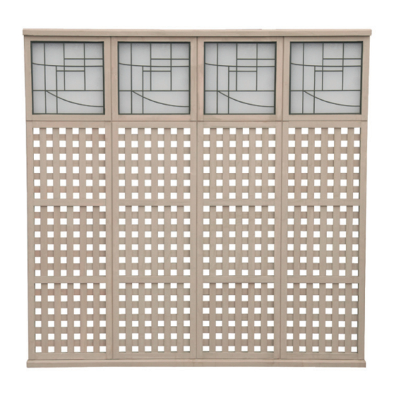
(2) One High Arch Topper and (2) of the above #8 x 2 1/4” Wood Screw #10 x 1” Pan Head Screw #8 x 1 1/2” Wood Screw (4) Three High Lattice Panel or, (4) Three High X Panel (6) Panel Clips Privacy & Decorative Panel Kits: 4 High Privacy Lattice / X Panel - YM11515 4 High Lattice with Faux Glass Panel - YM11517 4 High Privacy Lattice Panel - YM11540 4 High Decorative X Panel - YM11544 4 High Decorative X / Arch Panel - YM11548 4 High Privacy Lattice/ X / Arch Panel - YM11549... - Page 5 Step 1- Assemble Panels 1. R emove the upper metal connectors on both sides of P_3 - Three High_Panel. Reattach the metal connectors to P_3 by securing the bottom two holes of the metal connectors to the top two holes on P_3 so that the metal connectors stick out from the top. Slide P_1 – One High_Topper between the two protruding metal connectors on the top of P_3. Attach the metal connectors to P_1. (Fig. 1A) *Ensure Panels are oriented correctly! (Fig. 1B) 2. S ecure panels with a S4 - 2 1/4” Wood Screw the location indicated by the large...
- Page 6 Step 2- Assemble Wall Fig. 1 1. Assemble panels together in configuration shown. (Fig.1) Insert male connector into female. Slide down until flush with adjacent Instruc Assemble Toppers to Panels. Instructions de base Pautas básicas para Cut and attach T Pautas básicas para pour l' panel as shown. (Fig. 1A) Basic Guidelines el ensamblado de Instale los topes en los paneles.
- Page 7 Step 3- Installing Panel Clips 1. On a flat surface place P- 4x4 Post on its side and positio s i t i t s locations indicated in Figures 1 and 1A. Ensure Panel Cl as shown in Diagrams! 1. Postition Panel Clips in locations indicated in Figures 1 and 1A. Orient Panel Clips according to whether 2.
- Page 8 Step 4- Installing Wall Into Flat Roof Pergola 1. With the help of an adult, place the Wall on Panel Clips as shown (Fig.1) allowing a 4” gap between the bottom of the post and the bottom edge of the bottom rail on the panel assembly. 2. With a 1/8” drill bit, predrill holes as shown in figure 2. 3. F asten the Wall to the post and Panel Clips with a S5- 1” Pan Head Screw provided in location of arrows. (Fig. 1) Fig.
- Page 9 Step 4- Installing Wall Into Arched pergola 1. With the help of an adult, place the Wall on Panel Clips as shown (Fig.1) allowing a 1” gap between the bottom of the post and the bottom edge of the bottom rail on the panel assembly. 2. With a 1/8” drill bit, predrill holes as shown in figure 2. 3. F asten the Wall to the post and Panel Clips with a S5- 1” Pan Head Screw provided in location of arrows. (Fig. 1) Fig.
- Page 10 Step 4- Installing Wall Into Fence 1. With the help of an adult, place the Wall on Panel Clips as shown (Fig.1) allowing a 4” gap between the bottom of the post and the bottom edge of the bottom rail on the panel assembly. 2. With a 1/8” drill bit, predrill holes as shown in figure 2. 3. F asten the Wall to the post and Panel Clips with a S5- 1” Pan Head Screw provided in location of arrows. (Fig. 1) Fig.
Need help?
Do you have a question about the YM11515 and is the answer not in the manual?
Questions and answers