
Summary of Contents for Lars Thrane iridium LT-3100S
- Page 1 User & Installation Manual LT-3100S GMDSS Satellite Communications System Document Number: 95-101817 Rev. 1.02 Release date: January 8, 2020 Copyright © Lars Thrane A/S Denmark ALL RIGHTS RESERVED...
- Page 3 Manuals issued by Lars Thrane A/S are periodically revised and updated. Anyone relying on this information should acquire the most current version e.g. from Lars Thrane A/S. Lars Thrane A/S is not responsible for the content or accuracy of any translations or reproductions, in whole or in part, of this manual from any other source.
- Page 4 Failure to comply with these precautions or with specific warnings elsewhere in this manual violates safety standards of design, manufacture and intended use of the equipment. Lars Thrane A/S assumes no liability for the customer's failure to comply with these requirements. Instructions for the Installer...
- Page 5 Failure to comply with these precautions or with specific warnings elsewhere in this manual violates safety standards of design, manufacture and intended use of the equipment. Lars Thrane A/S assumes no liability for the customer's failure to comply with these requirements. Instructions for the Operator WARNING –...
- Page 6 - Consult the dealer or an experienced radio/TV technician for help. This product does not contain any user-serviceable parts. Repairs should only be made by an authorized Lars Thrane A/S service center. Unauthorized repairs or modifications could result in permanent damage to the equipment and void your warranty and your authority to operate this device under Part 15 regulations.
- Page 7 All safety instructions and guidelines in this manual must be observed. The safety instructions are listed in the beginning of the manual. The guidelines are to be found in the separate chapters, where it is needed. Lars Thrane A/S www.thrane.eu...
- Page 8 LT-3100S GMDSS User & Installation Manual Rev. 1.02 Software versions This manual is applicable to the following software: Software Versions Description Version LT-3100S GMDSS System 1.01 Table 1: Software Versions Lars Thrane A/S www.thrane.eu...
- Page 9 LT-3100S GMDSS User & Installation Manual Rev. 1.02 Record of Revisions Rev. Description Release Date Initials 1.00 Original document. November 4, 2019 1.01 GMDSS user functions November 19, 2019 KK, PT 1.02 Added FCC compliance notes, Part 80 (page iv) January 8, 2020 Lars Thrane A/S www.thrane.eu...
-
Page 10: Table Of Contents
Menu system ............................... 34 System status .............................. 36 Using the system ............................. 38 Distress Alert ............................... 38 Maritime Safety Information (MSI) ......................39 Priority voice call ............................39 Priority messaging ............................39 Non-priority voice call ..........................40 Lars Thrane A/S www.thrane.eu viii... - Page 11 App. K - Outline Drawing: Bracket Mount, Antenna Unit ................. 68 App. L - Outline Drawing: LT-3120 Handset ....................69 App. M - Outline Drawing: LT-3121 Cradle ....................70 App. N - EU Declaration of Conformity ...................... 71 Lars Thrane A/S www.thrane.eu...
-
Page 12: Introduction
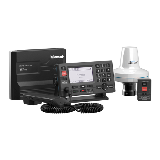
The LT-3100S GMDSS Satellite Communications System is a maritime satellite communication product from Lars Thrane A/S. The LT-3100S GMDSS system is designed for the professional market (deep sea, fishing, and workboats), but can be used for the leisure market as well. The LT-3100S GMDSS system meets all standards and certification requirements needed for worldwide maritime satellite communication equipment. -
Page 13: Unpacking (In-The-Box)
Satellite Communications System – Basic (P/N: 90-102071) and must be ordered separately. The antenna unit must only be mounted, using the bracket or pole mounted, delivered by Lars Thrane A/S. The antenna unit mounts are listed with part numbers (P/N) in Accessories on page 3. -
Page 14: Accessories
N connector. NOTE: For further details on the cable and connectors, please contact Lars Thrane A/S. A coaxial cable up to a length of 500 meters can be used for connecting the LT-3110S Control Unit and the LT-3130 Antenna Unit. Details about the coaxial cable, specification and cable lengths, are described in LT-3130 Antenna Unit on page 26. -
Page 15: System Overview
An overview of the LT-3100S GMDSS system is illustrated in Figure 1. Figure 1: LT-3100S GMDSS system - components and interfaces. The LT-3100S GMDSS system consists of the following units, provided by Lars Thrane A/S: • LT-3110S Control Unit •... - Page 16 The LT-3100S GMDSS system will be released to customers with the initial software version 1.01. Software version 1.01 includes support for all GMDSS services. Additional none GMDSS services might be added in later software releases. Please contact Lars Thrane A/S for details about future software releases and features: support@thrane.eu Lars Thrane A/S www.thrane.eu...
-
Page 17: Installation And Mounting
N connector (female) for coaxial cable to the LT-3130 Antenna Unit, marked ‘ANT’ • Ethernet (RJ-45) connector, marked ‘LAN’ • 10-pin auxiliary connector (male), marked ‘AUX’ • SIM card, marked ‘SIM’ • 5-pin connector (female) for LT-3120 Handset (front of the control unit) Lars Thrane A/S www.thrane.eu Page 6 of 71... - Page 18 Mount the unit on a rigid structure with a minimum of exposure to vibration and shock • Mount the unit in an area with an ambient temperature between -15°C to +55°C (+5°F to +131°F) Lars Thrane A/S www.thrane.eu Page 7 of 71...
- Page 19 Installation and Mounting The Bracket Mount and Flush Mount for the LT-3110S Control Unit are illustrated in Figure 4 and Figure 5. Figure 4: Bracket Mount, Control Unit. Figure 5: Flush Mount, Control Unit. Lars Thrane A/S www.thrane.eu Page 8 of 71...
-
Page 20: 3120 Handset
“Handset not connected”. NOTE: The LT-3120 Handset must be operated together with the LT-3121 Cradle, for the off-hook detection circuit to work. The LT-3121 Cradle is described in LT-3121 Cradle on page 10. Lars Thrane A/S www.thrane.eu Page 9 of 71... -
Page 21: 3121 Cradle
0.4 m (1.3 ft). An outline drawing for the LT-3121 Cradle is available in App. M - Outline Drawing: LT-3121 Cradle on page Lars Thrane A/S www.thrane.eu Page 10 of 71... -
Page 22: 3130 Antenna Unit
Mount the unit on a rigid structure with a minimum of exposure to vibration and shock • Mount the unit using either the Bracket Mount or Pole Mount provided by Lars Thrane A/S • Mount the unit outdoor with an ambient temperature between -40°C to +55°C (-40°F to +131°F) •... - Page 23 Maximum allowed torque is 2 Nm when connecting the coaxial cable N-connector (male) to the N-connector (female) of the LT-3130 Antenna Unit. No tooling must be used for fastening the coaxial cable thread nut as illustrated on Figure 11 above. Lars Thrane A/S www.thrane.eu Page 12 of 71...
- Page 24 LT-3130 Antenna Unit may be reduced, with no impact on the antenna performance. The performance of the LT-3130 Antenna Unit should be validated when the LT-3100S GMDSS system is installed. Lars Thrane A/S www.thrane.eu Page 13 of 71...
- Page 25 The LT-3130 Antenna Unit must be mounted using one of the following antenna mounts: • 91-100773 Bracket Mount (1.5” to 2.5” tube), Antenna Unit • 91-100774 Pole Mount (1.5” tube), Antenna Unit Lars Thrane A/S www.thrane.eu Page 14 of 71...
-
Page 26: 3140S Interface Unit
Use all four screw holes (every corner) of the backplate, to fasten the unit sufficiently. The LT-3140S Interface Unit interfaces are described in LT-3140S Interface Unit on page 28. Lars Thrane A/S www.thrane.eu Page 15 of 71... -
Page 27: 3150S Alarm Panel
Table 2: LT-3150S Alarm Panel Interconnect details. LT-3150S AP Interconnect Details Wire Color Wire Designation White Yellow CAN+ Green CAN- Brown See <reference> for operation of the DISTRESS button and activation of Distress Alert. Lars Thrane A/S www.thrane.eu Page 16 of 71... - Page 28 The LT-3150S Alarm Panel can be released from the bracket mount by using a release tool as illustrated in Figure 19 and Figure 18. Figure 19: LT-3150S Alarm Panel release tool Figure 18: LT-3150S Alarm Panel release tool Lars Thrane A/S www.thrane.eu Page 17 of 71...
-
Page 29: 3160S Printer Adapter
CAN+ Green CAN- Brown The LT-3160S Printer Adapter can be connected to the following list of GMDSS printers, which is verified by Lars Thrane A/S: Table 4: LT.3100S GMDSS System Supported GMDSS Printers Supported GMDSS Printers Manufacturer Model No. Furuno... -
Page 30: Bracket Mount, Antenna Unit
The torques are specified in Figure 24 on page 20. NOTE: The Bracket Mount (1.5” to 2.5” tube), Antenna Unit interfaces to a tube of maximum 2.5” (63.5 mm), measured outer diameter. Lars Thrane A/S www.thrane.eu Page 19 of 71... - Page 31 Figure 17. The bracket mount, V-bolts, and nuts are all made of A4 stainless steel Figure 24: Bracket Mount (1.5” to 2.5” tube), Antenna Unit – horizontal tube mount. Lars Thrane A/S www.thrane.eu Page 20 of 71...
-
Page 32: Pole Mount, Antenna Unit
Remember to fasten the antenna lock pinot screw (1.2 Nm) after the pole mount and antenna unit have been screwed together. NOTE: The Pole Mount (1.5” tube), Antenna Unit interfaces to a tube of maximum 1.5” (38.1 mm), measured outer diameter. Lars Thrane A/S www.thrane.eu Page 21 of 71... - Page 33 The Pole Mount (1.5” tube), Antenna Unit only support a 1.5” tube. The pinot screws (antenna and pole lock) torques are specified in Figure 26 and Figure 27. The pole mount is made of milled aluminum (anodized). The pinot screws are made of A4 stainless steel. Lars Thrane A/S www.thrane.eu Page 22 of 71...
-
Page 34: Interfaces
DC power to the LT-3100S GMDSS system is provided by connecting the proprietary 91-102118 power cable, 3m - delivered by Lars Thrane A/S. The power connector is mounted on the back side of the LT-3110S Control Unit and marked ‘PWR’, see Figure 3 on page 7. - Page 35 SIM card PIN code, then the SIM card default PIN code cannot be restored, and the new PIN code must be used to unlock the SIM card and the Iridium services. Lars Thrane A/S www.thrane.eu Page 24 of 71...
- Page 36 Web server on page 49. NOTE: Use only the 91-100768 Auxiliary Cable, 3m delivered by Lars Thrane A/S for connecting to the auxiliary connector on the backside of the LT-3110S Control Unit. The Auxiliary Cable, 3m is an accessory part and must be acquired separately.
-
Page 37: 3130 Antenna Unit
(10 W), and R is the total DC Cable resistance [ꭥ/km] (sum of inner and outer conductor resistance). Figure 29: Coaxial Cable Total DC Resistance vs. Cable Length (12 VDC and 24 VDC). Lars Thrane A/S www.thrane.eu Page 26 of 71... - Page 38 Lars Thrane A/S has calculated the maximum allowed cable lengths with two coaxial cables as illustrated in Table 6. The two cables are FF195LSFROH (~RG-58) and FF400LSFROH (~RG-214).
-
Page 39: 3140S Interface Unit
Electronic Chart Display and Information System (ECDIS) -> via RS-422 (NAV) • Ship Security and Alarm System (SSAS) Alarm Button -> via GPIO (up to 3 devices) • Ship Security and Alarm System (SSAS) Test Button -> via GPIO Lars Thrane A/S www.thrane.eu Page 28 of 71... - Page 40 ‘GNDC’, see Figure 30 on page 28. WARNING: Only DC input power: 12 to 24 VDC must be applied on the LT-3140S Interface Unit. Crimp tubes on the DC power cable must be used. Lars Thrane A/S www.thrane.eu Page 29 of 71...
-
Page 41: User Interface (Ui)
• Soft keys buttons: Three soft keys are available below the display. The soft keys are used for different purposes and their functions will change in the operation modes of the system. Lars Thrane A/S www.thrane.eu Page 30 of 71... -
Page 42: Display
Each slot shows the status of one function or group of functions. If a group of functions in a slot has more than one active icon, the slot will continuously take turn showing one icon at a time for a few seconds before cycling to the icon of the next function. Lars Thrane A/S www.thrane.eu Page 31 of 71... - Page 43 There are one or more missed calls. There are one or more voicemail messages. There are one or more unread SMS or E-mail messages. Table 10: LT-3110S Control Unit - UI notifications Lars Thrane A/S www.thrane.eu Page 32 of 71...
- Page 44 Table 11: LT-3110S Control Unit - UI input mode Miscellaneous Functions – Slot 6 A Bluetooth device is connected. The Tracking service is active. Table 13: LT-3110S Control Unit - UI miscellaneous functions Lars Thrane A/S www.thrane.eu Page 33 of 71...
-
Page 45: Menu System
Figure 34: LT-3110S Control Unit - UI display (main menu). The main menu is represented by four sub-menus: GMDSS, Phone, Settings, and System. The four sub- menus are listed in Table 15 on page 35. Lars Thrane A/S www.thrane.eu Page 34 of 71... - Page 46 Date & Time System Phone Setup Network Bluetooth (not for SOLAS) Tracking Security SIP Status GNSS Status Alert List System Information Power Supply Reset Options Table 15: LT-3110S Control Unit, sub-menu layout. Lars Thrane A/S www.thrane.eu Page 35 of 71...
-
Page 47: System Status
System Status 0 to 5 Registered Ready to use 0 to 5 Registering… Not ready No bars (with cross) Searching for Iridium… Not ready Table 16: LT-3110S Control Unit – Registration status. Lars Thrane A/S www.thrane.eu Page 36 of 71... - Page 48 SIM card format or data is wrong. Please power down the LT-3110S Control Unit, verify correct SIM card re-insert, and re- power the system again. Table 17: LT-3110S Control Unit – System Text Lars Thrane A/S www.thrane.eu Page 37 of 71...
-
Page 49: Using The System
The Nature of Distress can be assigned at any time before (MENU -> GMDSS -> Distress Alert Setup -> Nature of Distress) or after (soft key Select Nature / Update Nature) activation of Distress Alert. Lars Thrane A/S www.thrane.eu Page 38 of 71... -
Page 50: Maritime Safety Information (Msi)
4. In the priority dialog, select the priority of the message and press ENTER or the Select soft key 5. Enter the text of the message boxy 6. Press the Send soft key to send the message Lars Thrane A/S www.thrane.eu Page 39 of 71... -
Page 51: Non-Priority Voice Call
Figure 36: LT-3110S Control Unit – voice call (on-hook mode). On-hook mode (step-by-step): 1. Type in the called number (e.g. 004588301089) using the numeric keypad 2. When the called number is complete: Lars Thrane A/S www.thrane.eu Page 40 of 71... - Page 52 Using the system a. Lift the handset out of the cradle or b. Press the off-hook button (green handset button) 3. The LT-3100S GMDSS system will now establish a connection to the dialed number Lars Thrane A/S www.thrane.eu Page 41 of 71...
- Page 53 In case of problems with the satellite network or connection to the called party (far-end), the user will be informed through a voice prompt, and by status cause codes, that will be presented on the display (e.g. “Temporary link failure”). Lars Thrane A/S www.thrane.eu Page 42 of 71...
-
Page 54: Non-Priority Messaging
Figure 39: LT-3110S Control Unit – voice call successfully connected. Non-priority messaging Non-priority messages are sent from MENU -> Phone -> Messages. The system automatically receives non-priority messages. NOTE: Non-priority messages cannot be sent to an RCC. Lars Thrane A/S www.thrane.eu Page 43 of 71... -
Page 55: Position Of Vessel
BAM icon representing the alert with the highest priority is shown in the status bar (see Figure 40). The exact icon shown depends on the priority and state of the alert with the Figure 40: LT-3110S Control Unit - UI BAM status Lars Thrane A/S www.thrane.eu Page 44 of 71... - Page 56 The shape and color of the BAM icon indicates the priority of the alert and the symbol inside indicates its state as shown in Table 18 below. Lars Thrane A/S www.thrane.eu Page 45 of 71...
- Page 57 (and thus the audible signal), press the “Silence BAM” soft key. The temporary silence period expires after 30 s, after which active silenced alerts become active unacknowledged alerts again, causing the audible signal to resume. Lars Thrane A/S www.thrane.eu Page 46 of 71...
- Page 58 CAM system. When an alert has had its responsibility transferred to the CAM system, it can be acknowledged at the CAM system and its corresponding audible signal will only be heard at the CAM system. Lars Thrane A/S www.thrane.eu Page 47 of 71...
-
Page 59: Printing
If the LT-3160S Printer Adapter has been installed, the LT-3100S GMDSS system can be configured to automatically print MSI and/or priority messages on the printer. The LT-3100S GMDSS system can print the International Reference Alphabet (IRA) character set (also known as IA5 or T.50). Lars Thrane A/S www.thrane.eu Page 48 of 71... -
Page 60: Web Server
Figure 42: LT-3110S Control Unit - built-in web server (dashboard). The web server has the following web pages available: • Dashboard • GMDSS – MSI • Configuration • Software update • Diagnostic report • Legal notice • Log out Lars Thrane A/S www.thrane.eu Page 49 of 71... - Page 61 User & Installation Manual. NOTE: All web site functionality will be described in detail for the LT-3100S GMDSS system prior to customer release of this system. Lars Thrane A/S www.thrane.eu Page 50 of 71...
-
Page 62: Dashboard
152149.tar.gz will be downloaded to a location selected by the user. The diagnostic report can be sent back to Lars Thrane A/S in case of required support and assistance. The diagnostic report contains technical data, from the LT-3100S GMDSS system, and will help identify and resolve problems at the installation site. This is to avoid sending back the LT-3100S GMDSS system for unnecessary debug and repair, at the Lars Thrane A/S facility. -
Page 63: Accessing The Built-In Web Server
LT-3100S GMDSS System dashboard ‘Go on to the webpage (Not recommended)’. 6. You will now see the LT-3100S GMDSS system dashboard. Figure 44: Accessing built-in web server (“This site is not secure”). Lars Thrane A/S www.thrane.eu Page 52 of 71... -
Page 64: Service & Repair
This practice also applies for returning of products for service and repair. All information that will get back to Lars Thrane A/S, either directly or indirectly, will be handled with confidentiality. End-user sensitive data will not be shared with any third party without prior written acceptance from the involved parties. -
Page 65: Appendixes
Alert may be acknowledged at the alert source and/or the CAM system. Alert that cannot be acknowledged on the bridge but for which information is required about the status and treatment of the alert. Table 21: BAM alert categories Lars Thrane A/S www.thrane.eu Page 54 of 71... - Page 66 Raised when the terminal has been unable to detect or otherwise contact the Conditions: satellites of the Iridium® satellite system for a period of one minute or more. Rectified when the terminal detects the Iridium® satellite system. Lars Thrane A/S www.thrane.eu Page 55 of 71...
- Page 67 Read the received MSI message (see Maritime Safety Information (MSI) on page What to do: 39). Raised when a safety MSI message is received. Conditions: Rectified when all MSI messages of severity safety have been read. Lars Thrane A/S www.thrane.eu Page 56 of 71...
- Page 68 Verify the correct SIM card is inserted in the terminal. If the SIM card has been What to do: replaced, power-cycle the system and follow the instructions in the UI. Raised when an unknown SIM card is detected. Conditions: Rectified when the unknown SIM card is removed. Lars Thrane A/S www.thrane.eu Page 57 of 71...
-
Page 69: App. B - Specifications
IP rating, dust and water IP67 Interfaces Control Unit (N conn.) Iridium transmitter, Max RF output power Iridium transmitter, Frequency bands TX: 1616-1626,50MHz, RX: 1616-1626,50MHz Antenna communication cable Coaxial cable, up to 500 m (1500 ft) Lars Thrane A/S www.thrane.eu Page 58 of 71... - Page 70 62.1 x 68.1 x 19.4 mm (2.44 x 2.68 x 0.76 in) Temperature, operational -15°C to +55°C (+5°F to +131°F) IP rating, dust and water IP40 Interfaces 1 x CAN Warranty 2 year Maintenance None Lars Thrane A/S www.thrane.eu Page 59 of 71...
-
Page 71: App. C - Outline Drawing: Lt-3110S Control Unit
LT-3100S GMDSS User & Installation Manual Rev. 1.02 Appendixes App. C - Outline Drawing: LT-3110S Control Unit Figure 45: Outline Drawing: LT-3110S Control Unit Lars Thrane A/S www.thrane.eu Page 60 of 71... -
Page 72: App. D - Outline Drawing: Bracket Mount, Control Unit
LT-3100S GMDSS User & Installation Manual Rev. 1.02 Appendixes App. D - Outline Drawing: Bracket Mount, Control Unit Figure 46: Outline Drawing: Bracket Mount, Control Unit Lars Thrane A/S www.thrane.eu Page 61 of 71... -
Page 73: App. E - Outline Drawing: Flush Mount, Control Unit
LT-3100S GMDSS User & Installation Manual Rev. 1.02 Appendixes App. E - Outline Drawing: Flush Mount, Control Unit Figure 47: Outline Drawing: Flush Mount, Control Unit Lars Thrane A/S www.thrane.eu Page 62 of 71... -
Page 74: App. F - Outline Drawing: Lt-3130 Antenna Unit
LT-3100S GMDSS User & Installation Manual Rev. 1.02 Appendixes App. F - Outline Drawing: LT-3130 Antenna Unit Figure 48: Outline Drawing: LT-3130 Antenna Unit Lars Thrane A/S www.thrane.eu Page 63 of 71... -
Page 75: App. G - Outline Drawing: Lt-3140S Interface Unit
LT-3100S GMDSS User & Installation Manual Rev. 1.02 Appendixes App. G - Outline Drawing: LT-3140S Interface Unit Figure 49: Outline Drawing: LT-3140S Interface Unit Lars Thrane A/S www.thrane.eu Page 64 of 71... -
Page 76: App. H - Outline Drawing: Lt-3150S Alarm Panel
LT-3100S GMDSS User & Installation Manual Rev. 1.02 Appendixes App. H - Outline Drawing: LT-3150S Alarm Panel Figure 50: Outline Drawing: LT-3150S Alarm Panel Lars Thrane A/S www.thrane.eu Page 65 of 71... -
Page 77: App. I - Outline Drawing: Lt-3160S Printer Adapter
LT-3100S GMDSS User & Installation Manual Rev. 1.02 Appendixes App. I - Outline Drawing: LT-3160S Printer Adapter Figure 51: Outline Drawing: LT-3160S Printer Adapter Lars Thrane A/S www.thrane.eu Page 66 of 71... -
Page 78: App. J - Outline Drawing: Pole Mount, Antenna Unit
The Pole Mount (1.5” tube), Antenna Unit interfaces to a tube of maximum 1.5” (38.1 mm), measured outer diameter. The total weight of the Pole Mount is 0.18 kg (0.40 lbs). Figure 52: Outline Drawing: Pole Mount (1.5” tube), Antenna Unit Lars Thrane A/S www.thrane.eu Page 67 of 71... -
Page 79: App. K - Outline Drawing: Bracket Mount, Antenna Unit
The Bracket Mount (1.5” to 2.5” tube), Antenna Unit interfaces to a tube of maximum 2.5” (63.5 mm), measured outer diameter. The total weight of the Bracket Mount is 0.68 kg (1.50 lbs). Figure 53: Outline Drawing: Bracket Mount (1.5” to 2.5” tube), Antenna Unit Lars Thrane A/S www.thrane.eu Page 68 of 71... -
Page 80: App. L - Outline Drawing: Lt-3120 Handset
LT-3100S GMDSS User & Installation Manual Rev. 1.02 Appendixes App. L - Outline Drawing: LT-3120 Handset Figure 54: Outline Drawing: LT-3120 Handset Lars Thrane A/S www.thrane.eu Page 69 of 71... -
Page 81: App. M - Outline Drawing: Lt-3121 Cradle
LT-3100S GMDSS User & Installation Manual Rev. 1.02 Appendixes App. M - Outline Drawing: LT-3121 Cradle Figure 55: Outline Drawing: LT-3121 Cradle Lars Thrane A/S www.thrane.eu Page 70 of 71... -
Page 82: App. N - Eu Declaration Of Conformity
LT-3100S GMDSS User & Installation Manual Rev. 1.02 Appendixes App. N - EU Declaration of Conformity Not available yet (pending BABT approval) Lars Thrane A/S www.thrane.eu Page 71 of 71... - Page 83 Lars Thrane A/S Skovlytoften 33 2840 Holte Denmark www.thrane.eu...
Need help?
Do you have a question about the iridium LT-3100S and is the answer not in the manual?
Questions and answers