Table of Contents
Advertisement
Quick Links
Tel +1 (717) 767-6511
Fax +1 (717) 764-0839
www.redlion-controls.com
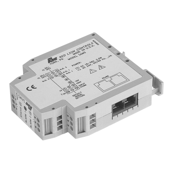
MODEL IAMS - INTELLIGENT ANALOG TO MODBUS CONDITIONER W/ ALARMS
GENERAL DESCRIPTION
The IAMS3535 Smart Analog to MODBUS Conditioner with Alarms
module accepts a wide range of DC analog process signals. There are eighteen
different DC analog input ranges which determine the input span and type. The
input accepts a maximum of 110 VDC and 110 mA DC.
The IAMS converts an analog input signal into a register format that can be
read using ASCII or RTU MODBUS protocol. With the features of gain and
offset, the input signal can be scaled to meet process requirements. Additionally,
two setpoint values can be entered for dual relay process monitoring alarms.
The IAMS is programmed with Windows™ based SFIMS software. The
software allows configuration, calibration, and storage of IAMS program files.
Additionally, all setup parameters can be interrogated and modified through
MODBUS register and coil commands.
The RS485 port allows the IAMS to be multidropped, with Baud rates up to
38400. The CBPRO007 programming cable converts the RS232 port of a PC to
RS485, and is terminated with an RJ-11 connector. The bidirectional capability
of the CBPRO007 allows it to be used as a permanent interface cable as well as
a programming cable.
The IAMS's two Form A relay alarms can be configured independently for
absolute high or low acting with balanced or unbalanced hysteresis. Alarm 2 can
also be configured for deviation and band alarms. In these modes, Setpoint 2
tracks Setpoint 1. Adjustable alarm trip delays can be used for delaying output
response. The alarms can be programmed for Automatic or Latching. Latched
alarms must be reset via serial command. A standby feature supresses the alarm
during power-up until the process stabilizes outside the alarm region. Standby
eliminates power-up tripping for low acting alarms. The output relays can also
be manually controlled via register commands.
The module's high density packaging and DIN rail mounting saves time and
panel space. The module is equipped with a universal mounting foot for
attachment to standard DIN rails, including top hat (T) profile or G profile rail.
DIMENSIONS In inches (mm)
ANALOG TO MODBUS CONVERSION
O
18 DIFFERENT DC ANALOG INPUT RANGES
O
PROCESSOR BASED SCALING
O
PC CONFIGURATION SOFTWARE
O
DUAL SETPOINT RELAY ALARMS
O
FOUR WAY SIGNAL ISOLATION
O
UL Recognized Component,
File # E179259
SAFETY SUMMARY
All safety related regulations, local codes and instructions that appear in the
manual or on equipment must be observed to ensure personal safety and to
prevent damage to either the instrument or equipment connected to it. If
equipment is used in a manner not specified by the manufacturer, the protection
provided by the equipment may be impaired.
CAUTION: Read complete
instructions prior to installation
and operation of the unit.
ORDERING INFORMATION
MODEL
DESCRIPTION
IAMS
Smart Analog to Modbus Conditioner w/Alarms
SFIMS
PC Configuration Software for Windows
CBPRO
Programming Interface Cable
Cable RJ11 to Unterminated 7 foot length
CBJ
Cable RJ11 to RJ11 6 inch jumper
-
RJ11 to Terminal Adapter
SPECIFICATIONS
1. POWER: 18-36 VDC, 3.0 W max. or 24 VAC, ± 10%, 50/60 Hz, 4 VA max.
2. INPUT DC RANGES:
0-20 mV, 0-50 mV, 0-100 mV, 0-200 mV, 0-500 mV, 0-1V, 0-2 V, 0-5 V,
0-10 V, 0-20 V, 0-50 V, 0-100 V, 0-2 mA, 0-5 mA, 0-10 mA, 0-20 mA,
0-50 mA, 0-100 mA
3. MAX. INPUT SIGNAL:
Current Input: 110 mA DC
Voltage Inputs: Terminal 7: 1 VDC +10%
Terminal 8: 10 VDC +10%
Terminal 9: 100 VDC +10%
4. INPUT RESISTANCE:
Current: 10 Ohms
Voltage: greater than 100 K
5. INPUT PROTECTION: Surge suppressor diode
Current Terminal: Protected to 110 mA DC max., 1.1 VDC.
100 V Terminal: Protected to 110 VDC.
1 V & 10 V Terminal: Protected to 100 VDC for one minute.
6. INPUT COMMON MODE REJECTION: 50/60 Hz, 110 dB min.
7. ISOLATION LEVEL: 1.5 kV @ 50/60 Hz, 1 min. between input, RS485
and power supply. 2300 Vrms, 1 min. to relay contacts.
1
Bulletin No. IAMS-A
Drawing No. LP0475
Released 9/01
CAUTION: Risk of electric shock.
PART NUMBER
IAMS3535
SFIMS
CBPRO007
CBJ11A07
CBJ11BD5
DRRJ11T6
Advertisement
Table of Contents

Subscribe to Our Youtube Channel
Related Manuals for red lion IAMS

Summary of Contents for red lion IAMS
- Page 1 110 VDC and 110 mA DC. equipment is used in a manner not specified by the manufacturer, the protection The IAMS converts an analog input signal into a register format that can be provided by the equipment may be impaired.
-
Page 2: Led Functionality
IEC 1010-1, EN 61010-1: Safety requirements for electrical equipment MODULE ISOLATION for measurement, control, and laboratory use, Part 1. The IAMS features “4-way” signal isolation. The 4-way isolation is a ELECTROMAGNETIC COMPATIBILITY combination of optical, transformer and relay barriers, providing common mode Immunity to EN 50082-2 voltage (CMV) isolation to 1.5 KV for 1 minute between input, RS485, and... -
Page 3: Step 1 Wiring The Module
DEFAULT SERIAL SETTING CONNECTION Module power is connected to terminals 1 and 2. For best results, the power If the IAMS settings are unknown, or forgotten, they can be reset to the should be relatively “clean” and within the specified limits. Drawing power factory defaults by connecting the Serial Default terminal 11 to Input Comm. -
Page 4: Step 3 Programming - Getting Started
STEP 4 PROGRAMMING THE INPUT The IAMS receives an analog input, converts it to a raw digital value, and stores this number in the ADC Value (register 40001). This number is scaled into engineering units using the Gain Value (register 40010) and Offset Value (register 40011). The result of this scaling is stored as the Process Value (register 40002). - Page 5 The Scaling Wizard prompts you to enter four values. Simply key in the Minimum and Maximum signal Input Values, and the desired Process Value equivalents. Press the Next button to calculate the new Gain and Offset values. Note: The Process Values must be between –32000 and +32000. (negative values will be transmitted as 2’s complement) Once the Next key is pressed, the software will display the new Gain and Offset values.
- Page 6 SETPOINT ALARM FIGURES STEP 6 PROGRAMMING THE IAMS COMMS PORT The IAMS’ serial port must match the device being used to communicate to it. MODBUS Protocol: RTU or ASCII Unit Address: 1-247 Baud Rate: 300, 600, 1200, 2400, 4800, 9600, 19200, or 38400...
-
Page 7: Step 7 Pc Port Configuration
Data Bits: 7 or 8 Parity: odd, even, or none Connect the IAMS to the computer with the CBPRO007 interface cable (or any suitable RS232/RS485 converter). Apply 18-36 VDC to the supply terminals of the IAMS. Note: The CBPRO007 download cable DOES NOT typically require power. In most cases it will derive its power from the PC. If communications can not be established, follow the troubleshooting guide. -
Page 8: Step 9 Scratch Pad Memory
When using SFIMS for calibration, connect the signal source to the IAMS, select the proper range in the software, and press the Calibrate button. Follow the calibration procedures in the software. -
Page 9: Troubleshooting
Provide a common connection NOTE: The IAMS’ serial settings must match the device that it is communicating with. If you do not know or cannot recall the IAMS settings, they can be reset back to factory defaults. Simply jumper the Serial Default terminal to Common, and cycle power. -
Page 10: Installation
When the flow is below a certain level, the IAMS switches the Main Pump off, and the Backup Pump on. Operators can monitor the flow and change the setpoints from the main building using a PC acquisition program with a MODBUS driver. -
Page 11: Modbus Information
MODBUS INFORMATION The remaining sections of this bulletin list IAMS Register Format information and MODBUS conformity. MODBUS SUPPORTED FUNCTION CODES SUPPORTED EXCEPTION CODES FC01: Read Coils 01: Illegal Function 1. Valid coil addresses are 1-16. Issued whenever the requested function is not implemented in the unit. - Page 12 40026 Factory Calibration <0000> <7777> Read/Write See Calibration explanation. IAMS-3535, 0100 (ver. 1.00), 16 reads, 16 writes, 16 scratch. It is possible that 41001- 41010 Slave ID See FC17. See FC17. Read Only the version value is higher. This area is for the user to store any related information.
- Page 13 0 / 1 <3D> <BD> 19200 0 / 1 <3E> <BE> 38400 0 / 1 <3F> <BF> * When reading register 40023, B7 will be a 0. When writing (changing IAMS communications to the new setting), change B7 to a 1.
- Page 14 <7D> <FD> ASCII 19200 0 / 1 <7E> <FE> ASCII 38400 0 / 1 <7F> <FF> * When reading register 40023, B7 will be a 0. When writing (changing IAMS communications to the new setting), change B7 to a 1.
- Page 15 This page intentionally left blank...
- Page 16 The customer agrees to hold Red Lion Controls harmless from, defend, and indemnify RLC against damages, claims, and expenses arising out of subsequent sales of RLC products or products containing components manufactured by RLC and based upon personal injuries, deaths, property damage, lost profits, and other matters which Buyer, its employees, or sub-contractors are or may be to any extent liable, including without limitation penalties imposed by the Consumer Product Safety Act (P.L.
Need help?
Do you have a question about the IAMS and is the answer not in the manual?
Questions and answers