Table of Contents
Advertisement
Quick Links
Operating Manual for OPTOCORE X6R/V3R-FX-INTERCOM
X6R/V3R-FX-INTERCOM – Intercom device for Optocore and SANE
Operating Manual
Rev. 2.8
- IC422 for Clear-Com
- IC485 for RTS
ICAES for AES/EBU based intercom
-
- IC444 for Audio and GPIO
Intercom devices for Optocore and SANE
© Copyright 2020 All rights reserved
OPTOCORE GmbH
Alte Allee 28
81245 Munich
Germany
Advertisement
Table of Contents

Summary of Contents for Optocore X6R-FX-INTERCOM
- Page 1 ICAES for AES/EBU based intercom - IC444 for Audio and GPIO Intercom devices for Optocore and SANE © Copyright 2020 All rights reserved OPTOCORE GmbH Alte Allee 28 81245 Munich Germany X6R/V3R-FX-INTERCOM – Intercom device for Optocore and SANE Operating Manual Rev. 2.8...
- Page 2 Page intentionally left blank.
-
Page 3: Important Safety Instructions
Never switch on power amplifiers before the complete system is stable and the level meters of • the OPTOCORE CONTROL software indicate a normal level. Do not place this device on an unstable table, tripod, cart, etc. The device may fall, causing •... -
Page 4: Owner Information
Leave sufficient space (minimum ½ RU) between the device and any heat emitting devices housed in the same rack. An Optocore device may be placed above or below other Optocore products, without a space between the devices for up to 4 adjacent rack spaces. - Page 5 Cleaning • To clean the device, use a dry linen cloth. If the unit is very dirty, lightly moisten a cloth using water and a small amount of household detergent. Never use cleaning agents containing solvents to clean the device. Operating and Storage Temperature •...
- Page 6 Such operation can lead to damage of the device’s components due to lack of air-flow through the device. The device may not be serviced, altered or modified without authorisation from Optocore or an Optocore authorised distributor / dealer. Only qualified service personnel may carry out repair and maintenance work on the device.
-
Page 7: Ce/Fcc-Conformity
Operation of this equipment in a residential area is likely to cause harmful interference, in which case you will be required to correct the interference at his own expense. Changes or modifications not expressly approved by Optocore GmbH could void the user’s authority to operate this equipment. - Page 8 Page intentionally left blank.
-
Page 9: Table Of Contents
Example 2 – Remote line level audio and GPIO ..................21 Example 3 – Trunking between Intercom Matrices ..................22 Example 4 – Two-wire PartyLine intercom over Optocore ................23 Connection Tables ..............................24 Connection Examples GPI/GPO IC444 Module ..................28... - Page 10 Technical Specifications ............................29 Dimensions and Weight ............................31 Warranty and Liability .............................. 32 Package Contents ..............................33 Contact Information ..............................33 X6R/V3R-FX-INTERCOM 10 / 33 rev. 2.8...
-
Page 11: Device Description
Congratulations on your purchase of an X6R/V3R-FX-INTERCOM, a dedicated interface for intercom connectivity to Optocore and SANE networks. The X6R/V3R-FX-INTERCOM series manual will quickly demonstrate the advantages of the device and help ease your day to day workload in the professional audio visual environment. - Page 12 Word Clock input and output connectors allow the Optocore network to be synchronized from an external source as well as for Word Clock be distributed around a facility using the Optocore network. All Optocore and SANE devices are capable of being system masters using their internal clock.
-
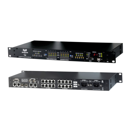
Page 13: Front Panel
Communication is established on the SANE 1 port (rear panel) SL2: Communication is established on the SANE 2 port (rear panel) OL1: Communication is established on the Optocore LINK 1 (rear panel) OL2: Communication is established on the Optocore LINK 2 (rear panel) Master LED:... - Page 14 USB plug and LED: USB connection for remote control and update via PC Green: Indicates data activity RS232 plug: D-Sub-9 RS232 connection for remote control and update via PC LAN LINK: Ethernet communication is established via SANE 1 (rear panel) Ethernet communication is established via SANE 2 (rear panel) There is other device with physical Ethernet port enabled on the network Ethernet communication is established via LAN 1 (rear panel)
-
Page 15: Rear Panel
RS485/GPIO: 4 x RS485/GPIO (D-Sub-9) auxiliary port for data transmission Word Clock IN: BNC Word clock input allowing synchronization of Optocore devices/network from an external word clock source Word Clock OUT: BNC Word clock output for synchronization of external devices POWER 2: Mains input for power supply 2 (100 …... -
Page 16: X6R-Fx-Intercom-Ic444
RS485/GPIO: 4 x RS485/GPIO (D-Sub-9) auxiliary port for data transmission Word Clock IN: BNC Word clock input allowing synchronization of Optocore devices/network from an external word clock source Word Clock OUT: BNC Word clock output for synchronization of external devices POWER 2: Mains input for power supply 2 (100 …... -
Page 17: Device Details
Transmission Delay The Optocore system delay, including the matrix, is a fixed 41,6 µs @ 48 kHz for all channels. The additional transport delay per Optocore unit on the network (<200 ns) is insignificant in comparison. Overall system delay is dependent on the converters used and the length of network cables in the system. -
Page 18: Power Supply
Control All system and device parameters are configured using the OPTOCORE CONTROL software. The system can be configured and controlled centrally, over the Optocore network, with the exception of the initial configuration of the unique identifier (ID) of the device. -
Page 19: Connectors And Cables
> 40 dB between 30 MHz up to 1 GHz. The shield of the cable should have contact to the connector hood. USB Connection Use a USB-A to USB-B cable between the PC and the Optocore device. LAN Connection Use a standard twisted pair cable (Cat-5, Cat-6) with RJ-45 connectors. -
Page 20: Hardware Connection
The following example demonstrates the use of X6R/V3R-FX-INTERCOM devices with intercom matrix systems. An X6R-FX-INTERCOM is connected to eight four-wire ports of a central intercom matrix. The four-wire ports, along with RS422 or RS485 control signals (device dependent), are distributed over the fully routable Optocore redundant ring topology network to remote locations. -
Page 21: Example 2 - Remote Line Level Audio And Gpio
The following example demonstrates the use of X6R/V3R-FX-INTERCOM devices with intercom matrix systems. An X6R-FX-INTERCOM is connected to eight four-wire ports of a central intercom matrix. The four-wire ports, along with GPIO control signals (device dependent), are distributed over the fully routable Optocore redundant ring topology network to remote locations. -
Page 22: Example 3 - Trunking Between Intercom Matrices
A pair of V3R-FX-INTERCOM devices is used to establish an eight channel trunk between two intercom matrices. The four-wire ports are transported over a fully routable Optocore redundant ring topology network. Control for both intercom matrices are connected together using the Optocore network’s internal Ethernet switch with an optional connection to a third party trunk controller. -
Page 23: Example 4 - Two-Wire Partyline Intercom Over Optocore
The PartyLine is created by routing bi-directional audio between PartyLine interface A, connected to the first Optocore device in the network, to PartyLine interface B, connected to the second Optocore device in the network. This is repeated throughout the Optocore network. -
Page 24: Connection Tables
Connection Tables Pin-out Four-Wire Intercom port - TO PANEL – ClearCom (IC422) Channel Audio In Audio Out RS422 In RS422 Out Use this pin-out only for devices loaded with ClearCom modules (IC422) RJ-45 Pin-out Four-Wire Intercom port - TO MATRIX – ClearCom (IC422) Channel Audio In Audio Out... - Page 25 Pin-out Four-Wire AES port - TO PANEL – AES based intercom systems (ICAES) Channel Use this pin-out only for devices loaded with AES modules (ICAES) RJ-45 Pin-out Four-Wire AES port – TO MATRIX – AES based intercom systems (ICAES) Channel Use this pin-out only for devices loaded with AES modules (ICAES) RJ-45...
- Page 26 A device compatible with “MADI” In “MADI” Out 10/100MB Fast Ethernet can be connected to a SANE port for Ethernet data communication. RJ-45 Pin-out Optical Fibre-Port Optocore LC connectors Pin-out RS232 - Port RS232 Power Internally Channel bridged Use standard RS232 cable, +5VS male –...
- Page 27 Pin-out DC Input – Factory Fitted Option XLR 4 Pin male X6R/V3R-FX-INTERCOM 27 / 33 rev. 2.8...
-
Page 28: Connection Examples Gpi/Gpo Ic444 Module
Connection Examples GPI/GPO IC444 Module X6R/V3R-FX-INTERCOM 28 / 33 rev. 2.8... -
Page 29: Technical Specifications
USB 2.0 – Device 12 Mbit/s IEEE - 802.3 10/100 Mbit/s SANE, LAN Convention Audio TIA - 568A/B, Optocore 200 Mbit/s TIA - 568A/B, IEEE - 802.3 10/100 Mbit/s Optical Connection Complies with 21 CFR 1040.10 and 1040.11 X6R/V3R-FX-INTERCOM 29 / 33... - Page 30 Power supply Type Switch-mode, universal input Mains voltage 100 … 240 V Frequency 50 … 60 Hz Power consumption Depending on the configuration of the device, 32VA - Max Security classification Class 1: basic insulation, connected to the protective grounding conductor Security regulations Harmonised European standard EN60065 Mains connector...
-
Page 31: Dimensions And Weight
Dimensions and Weight Dimensions Front panel: width 483 mm / 19 inch height 44 mm / 1.73 inch depth 200 mm / 7.87 inch Rear panel: width 438 mm / 17.25 inch Weight 2.7 kg ≡ 4.41 lbs Please note: Modifications that serve the purpose of technical improvement may be carried out without prior notification. -
Page 32: Warranty And Liability
The warranty will be void if you tamper with internal components. Please address any questions or inquiries to OPTOCORE or your distributor/dealer. For a full warranty conditions refer to the Warranty Card attached to every Optocore device with a first shipment. How to Obtain Warranty Service When discovering a problem with an OPTOCORE device, you should contact either Optocore directly or a dealer/distributor to determine and confirm a hardware fault. -
Page 33: Package Contents
Please note that due to the Ecology reason standard shipment does not contain printed copy of User Manual. All latest OPTOCORE user manuals can be downloaded from the website: http://www.optocore.com/index.php/support/downloads Printed version of User Manual is available on a special demand. Please contact support@optocore.com...
Need help?
Do you have a question about the X6R-FX-INTERCOM and is the answer not in the manual?
Questions and answers