Table of Contents
Advertisement
Quick Links
Advertisement
Table of Contents

Summary of Contents for ADENDORFF TRE-85
- Page 1 TRE-85 TAMPING RAMMER Operation manual Dynamic world Dynamic life...
-
Page 2: Table Of Contents
CONTENTS Contents ……………………………..…………………………………………1 Forward …………………………….………………………………………… 2 Feature…………………………………………………………………………2 Specification…………………………….……………………………………3 Safety precautions……………………..…………………………………… 3 Transporting and storage……………………………………………………5 Before operation checks………………………………………………………6 1. Check the engine………………………………………………………6 2. Check engine oil ……………………………………………………… 6 3. Check air cleaner…………………..……………………………………7 4. Check fuel…………………………….…………………………………7 Starting the engine……………………..………………………………………8 Operation………………………………….…………………………………11 Stop the engine………………………………………………………………12 Periodic Maintenance Schedule ……………………………………………13 1. -
Page 3: Feature
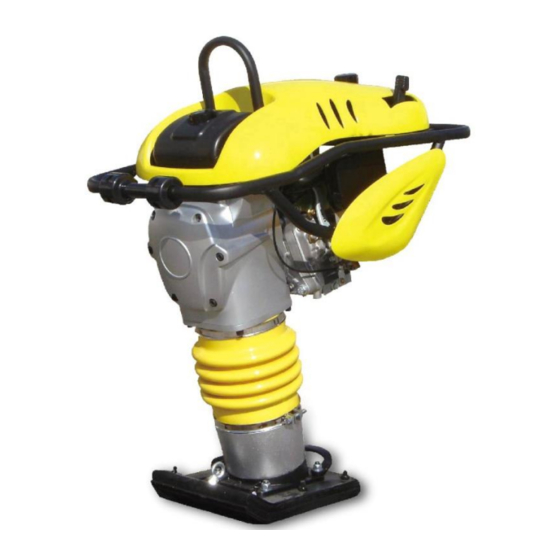
Easy for dismounting, and low cost for maintenance. TRE-85 Series Rammer are ideally suited for the compaction of granular, detritus, mixed and cohesive soils in confined areas, as well as apply to asphaltum detritus, concrete and clunch. -
Page 4: Specification
SPECIFICATION Weight: 80Kg Compacting force: 16000N Jump height: 50-60mm Forward speed: 8m/min Metal sheet: 280mm×350mm Engine: Air-cooled, 4-cycle, Gasoline Engine type: HONDA GX 120 or Robin EH-12 Overall dimensions: 750mm×420mm×1070mm Engine oil: Grade of Engine oil SF or SG; SAF10W-30 Engine oil: 0.40L Fuel: Unleaded gasoline with a pump octane rating of 90 or higher Fuel capacity: 3L... - Page 5 e. Keep the exhaust pipe free of foreign objects. 3. Refueling precautions: a. Be sure to stop the engine prior to refueling. b. Do not overfill the fuel tank. c. If fuel is spilt, wipe it away carefully and wait until the fuel has dried before starting the engine.
-
Page 6: Transporting And Storage
The following should be taken to prepare your TRE-85 Tamping Rammer for extended storage. 1、Close fuel shut off valve. 2、 Store the unit in an upright position in a cool, dry, well ventilated area. -
Page 7: Before Operation Checks
4、 Engine oil a. Change the engine oil fresh oil (see page 10). b. Remove the spark plug, pour about 5cc of engine oil into the cylinder, slowly pull the starter handle of the recoil starter 2 or 3 times, and reinstall the spark plug. 5、... -
Page 8: Check Air Cleaner
cause engine damage. 3. Check air cleaner NOTICE! Operating the engine without an air filter, or with a damaged air filter, will allow dirt to enter the engine, causing rapid engine wear. This type of damage is not covered by the Distributor’s Limited Warranty. 4. -
Page 9: Starting The Engine
5. Check the oil level sight plugs on the Pipe-protective r daily to ensure the oil is half way on the site glass. Tamping Rammer capacity is 50 oz. (1600ml). The band of lubrication: SAE10-30. 6. Check fastening screws of protective frame and central suspension for tight fit. - Page 10 5.Pull the starter grip lightly until you feel resistance. This is the “compression” point. Return the starter grip to its original position and pull swiftly. CAUTION!Do not allow the starter grip to snap back against the engine. Return it gently to prevent damage to the starter. After starting the engine, allow the starter grip to return to its original position while still holding the starter grip.
-
Page 11: Operation
OPERATION 1. After the engine starts, set the speed throttle lever at the low speed position and warm it up without load for a few minutes. Gradually move the speed throttle lever toward the high speed position and set it at the required engine speed. -
Page 12: Stop The Engine
STOP THE ENGINE 1. Set the speed throttle lever at the low speed position and allow the engine to run at low speed for 2 or 3 minutes before stopping. 2. Turn the STOP SWITCH counter-clockwise to the position “O” (OFF). 3. -
Page 13: Periodic Maintenance Schedule
PERIODIC MAINTENANCE SCHEDULE Warning! a. Make sure the machine is off before you begin any maintenance or repairs. b. These machine should be serviced by your servicing dealer or our company service department, unless you have the proper tools and mechanically proficient. -
Page 14: Maintenance Schedule
slowly and equably remove two nut(M12). See right fig. CAUTION!Keep people away from in the front two stud when remove spring, serious injury. CAUTION!Do not allow two stud to turn when remove spring. Be careful bounce. 2. Maintenance schedule Engine: Each After 1 Every... -
Page 15: Engine Oil Change
Combustion Clean-adjust Every 300 hrs chamber √ Fuel tank & Clean filter Every 2 years (Replace if necessary) Fuel tube Check Tamping rammer: Each After month Every 6 Every year or 50 hrs months or 150 or 300 hrs √ Check the oil lever sight plugs √... -
Page 16: Cleaning Fuel
b. Allow the used oil to drain completely, then reinstall the drain plug, washer, and tighten drain plug securely. Notice! Please dispose of used motor oil in a manner that is compatible with the environment. We suggest you take used oil in a sealed container to your local recycling center or service station for reclamation. -
Page 17: Spark Plugs
Saturate it in a mixture of 3 parts kerosene or diesel fuel and 1 part engine oil. Shake off excessive oil and reinstall. c. If an oil bath or special air cleaner with precleaner is used, clean the oil pan, fill oil to the required level or clean the dust pan. 6. -
Page 18: Fuel Pipe Replacement
6). Attach the spark plug cap. 7. Fuel pipe replacement Replace the fuel pipe every 2 years. When fuel leak is found replace it immediately. TROUBLESHOOTING 1. When engine will not start: a. The engine switch is OFF position. b. No fuel in tank c. - Page 19 ◇ In case the engine does not start with well supplied fuel, try using fresh fuel. f. Is there a strong spark across the electrode? Warning! Wipe out spilled fuel carefully before testing. Place spark plug as far away from spark plug hole as possible. Warning! Do not hold spark plug by hand while pulling recoil starter.
-
Page 20: Diagram
DIAGRAME: 1.Complete tamping Rammer: - 20 -... - Page 21 Item Part Drawing number Description TRE85-19-01 Head Cover TRE85-18-07 Tube TRE85-18-06 Clamp TRE85-24 Board Air cleaner Assembly Housing-crankcase TRE85-18 Assembly TRE85-11 Connecting Rod Guide Assembly GB/T70.1-2000 Screw (M6×20) TRE85-16 Handle Assembly GB/T923-76 NutM6 GB/T93-1987 Gasket( 6) Valve TRE85-23 Hose GB/T5783-2000 Bolt( M6×40) TRE85-27 LH Board...
- Page 22 2. Air cleaner Assembly: Drawing number Item Part Description TRE85-18-01 10401 Wave Handle O-Ring (11×1.9) GB/T1235-1976 10402 TRE85-18-02 10403 Cover TRE85-18-03 10404 TRE85-18-04 10405 Air cleaner GB/T70.1-2000 10406 Screw (M8×35) TRE85-18-05 10407 - 22 -...
- Page 23 3. Housing-crankcase Assembly: - 23 -...
- Page 24 Drawing number Item Part Description GB/T893.1-1986 10601 Retaining Ring (62) GB/T894.1-1986 10602 Retaining Ring (24) GB/T276-1994 10603 Bearing (6305) TRE85-15 10604 Gear-crank GB/T893.1-1986 10605 Retaining Ring (80) GB/T276-1994 10606 Bearing (6208) GB/T894.1-1986 10607 Retaining Ring (38) GB/T290-1998 10608 Bearing (HKH3520) GB/T70.1-2000 10609 Screw (M10×25)
- Page 25 4. Guide Assembly: - 25 -...
- Page 26 Drawing number Item Part Description GB/T1235-1976 10701 O-ring(105×3.1) TRE85-08 10702 Guide Cylinder GB/T70.1-2000 10703 Screw(M10×30) TRE85-28 10704 Clamp GB/T39-1988 10706 Nut(M10) GB/T5783-2000 10707 Bolt(M10×30) TRE85-06 10708 Bellow TRE85-01-03 10709 Pipe-protective 10710 Oil Gauge GB/T5783-2000 10711 Bolt(M10×16) GB/T70.1-2000 10712 Screw(M8×25) TRE85-10 10714 Pin-piston Mount TRE85-05-01...
- Page 27 10730 TRE85-01-01-01 Kit-roller GB/T70.1-2000 10731 ScrewM8×20 10732 TRE85-01-01 Rammer assembly 10733 GB/T6182-2000 LocknutM10 10734 GB/T95-1985 Washer 10 10735 TRE85-01-01-05 Linking piece 10736 TRE85-01-01-03 Wooden sheet 10737 TRE85-01-01-02 Metal sheet 10738 GB/T10-1988 Bolt M12×65 10739 GB/T10-1988 Bolt M10×60 10740 GB/T10-1988 Bolt M12×80 10741 Rings Nut M10 - 27 -...
- Page 28 Handle Assembly: Drawing number Item Part Description 11001 GB/T5783-2000 Bolt (M8×16) 11002 GB/T93-1987 Gasket (8) 11003 TRE85-26 Shock mount 11004 GB/T5783-2000 Screw (M8×25) - 28 -...
- Page 29 11005 GB/T70.2-2000 Screw( M8×12) 11006 TRE85-16-01 Kit-guide handle 11007 VP1550-15-01 Rubber Block 11008 GB/T70.1-2000 Screw (M6×16) 11009 TRE85-25 Kit-roller 11010 GB/T6183-2000 Locknut (M6) 11011 Cable-throttle 11012 GB/T5783-2000 Bolt (M8×40) 11013 GB/T5782-2000 Gasket (8) 11014 GB/T70.1-2000 Screw (M8×20) 11015 TRE85-22-01 Timing pole 11016 TRE85-22-03 Washer...
- Page 30 Clutch: Drawing number Item Part Description 11701 Nut-lock 11702 TRE85-09-06 Washer 11703 TRE85-09-04 Spring 11704 TRE85-09-05 Clutch 11705 TRE85-09-03 Centric 11706 TRE85-09-02 WasherⅡ 11707 TRE85-09-01 WasherⅠ 11708 Engine 11709 GB/T93-1987 Gasket(10) 11710 GB/T5783-2000 Screw(M10×55) - 30 -...
- Page 31 - 31 -...
- Page 32 We provide below machines CONCRETE PROCESSING SCREED POWER TROWEL RIDE-ON POWER TROWEL CONCRETE CUTTER CONCRETE VIBRATOR VIBRATOR POKER POLISHING MACHINE FLOOR GRINDER ROAD PLANER ASPHALT & CLAY COMPACTION RIDE-ON ROLLER VIBRATORY ROLLER LIGHT TOWER PLATE COMPACTOR REVERSIBLE PLATE TAMPING RAMMER MORTAR CONVEYING &...
Need help?
Do you have a question about the TRE-85 and is the answer not in the manual?
Questions and answers