Advertisement
DOC-FW821 -UM R1.0
Installation and Operation Manual
DESCRIPTION
The input-Output module FW821 is a UL listed device
according to UL864 and ULC-S527 for Fire Protective
Signaling Systems for indoor use. FW821 provides one
24VDC output and in addition one feedback input switch.
The input line is monitored for open line faults and
ground faults and the contact must thus be wired with an
end of line resistor. The output line is monitored for open
line, short circuit faults, ground faults, external 24VDC
power source loss and an end of line resistor is needed
as well.
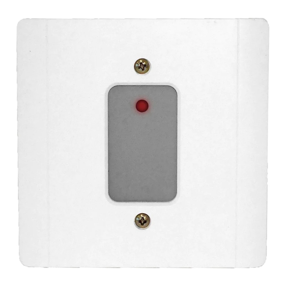
When the output is activated or the feedback is switched,
the device LED will indicate the event condition by fast
blinking.
A return to normal condition will cause the event to
disappear and the device LED indicator will return to the
red idle condition.
The FW821 is intelligent addressable and takes one
address on the Signaling Line Circuit (SLC) of the fire
alarm control panel.
SPECIFICATION
SLC Nominal Voltage
SLC Voltage Range
Standby Current
Active Current (SLC)
External Input Power Supply
External Input Power Supply
Active Current (Output)
Output Range
(Special Application)
Max. Line Impedance (Input)
Max. Line Impedance (Output)
FW821 Input-Output Module
24VDC
15 to 28VDC
0.15 mA
0.26 mA
24VDC (nominal)
15.4 to 24.4VDC (range)
80 mA, 0.35pf
15.0 to 24.0VDC
(Supplied by Model FW106
Auxiliary power output);
20.0 to 25.9VDC
(Supplied by Listed 24VDC
Regulated power supply).
25 Ω
1 Ω
MAPLE ARMOR FIRE ALARM DEVICE CO., LTD.
8866 Boul. du Quartier, Brossard, Quebec, Canada J4Y 0R2
www.maplearmor.com
Max. Impedance for Grounding
Compatible EOLR
Operating Temperature
Mounting
Operating Humidity
Dimension
Weight (with back box)
Wiring Gage
PROGRAMMING
The module must be programmed to a valid address
before use. A valid address means the address must be in
1~252 and can't be duplicate with other device in same
loop. Please use the hand-held programmer ReadWritor
FW411 to set device address.
Disconnect wire at terminal 1, 2, 3 and 4 before
programming.
INSTALLATION
• Mount the base, FW800, onto a 2X4 or 4x4 electrical
box using the screws provided, as illustrated in Figure
1.
Figure 1 Installation Diagram
• Connect the wires, see Figure 2. There is polarity
sensitive between terminal 1 and terminal 2. The
1/2
6.6 KΩ
FW421 (10KΩ)
32°F to 120°F (0°C to 49°C)
FW800 base
0% to 93% RH
120mm(L) x120mm(W) x
45mm(H)
9.2 oz (261g)
12 to 18 AWG
Advertisement
Table of Contents

Summary of Contents for Maple Armor FW821
- Page 1 FW821 Input-Output Module DESCRIPTION Max. Impedance for Grounding 6.6 KΩ Compatible EOLR FW421 (10KΩ) The input-Output module FW821 is a UL listed device Operating Temperature 32°F to 120°F (0°C to 49°C) according to UL864 and ULC-S527 for Fire Protective Mounting FW800 base Signaling Systems for indoor use.
- Page 2 Figure 3 SLC Wiring Diagram installation and testing is the sole responsibility of the • Combine the assembled unit to the base using the user. Maple Armor will not assume any liability for such screws provided. • use. In no case will Maple Armor’s liability exceed the Apply power to the control unit.
Need help?
Do you have a question about the FW821 and is the answer not in the manual?
Questions and answers