
Summary of Contents for SYCLOPE HYDRO'pH
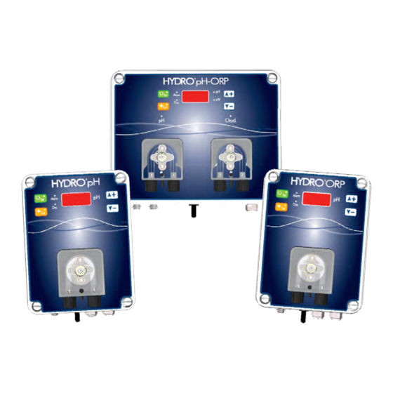
- Page 1 ® ® HYDRO’pH , HYDR’ORP ® and HYDRO’pH/ORP pH and ORP analyzers/controllers for private swimming pools Installation, commissioning, maintenance and programming instructions...
- Page 2 64 230 SAUVAGNON - France – Tel: (33) 05 59 33 70 36 Numéris concentrated phone lines Fax: (33) 05 59 33 70 37 Email: syclope@syclope.fr Internet: http:www.syclope.fr © 2012 by SYCLOPE Electronique S.A. Subject to change. ________________________________________________________________________________________________ ® ® ®...
-
Page 3: Table Of Contents
Page : 3 SUMMARY General information ..........................5 1.1. Using this document ............................... 6 1.2. Warranty ..................................6 Safety Instructions ..........................7 2.1. Controllers use ................................7 2.2. User’s obligations ................................ - Page 4 Page : 4 Changing set points of pH and/or ORP controller ................... 33 Faults reset ................................34 Testing the metering pump(s) ..........................34 Change the brightness of display and LEDs ..................... 34 ...
-
Page 5: General Information
If you need more information or if you encounter problems that not have been specified in this guide, please quickly contact your retailer or SYCLOPE Electronique S.A. sales department, either at the agency or office in your area, or at technical/quality service at our head office. We will do our best to help you and make you enjoy our advice and our knowledge in the field of measurement and treatment of pools water. -
Page 6: Using This Document
Page : 6 1.1. Using this document Descriptions are written in plain text Elements of lists are identified with commas (√) and the subcategories with dashes (-). The various stages of handling are identified by horizontal triangles (►) and secondary stages by points (●). -
Page 7: Safety Instructions
ORP potential by using specific sensors and suitable metering pumps under the options of use described in this manual. WARNING Any other use is considered non-compliant and must be outlawed. SYCLOPE Electronique will not provide, in any way, the liability and damages that could result. 2.2. User’s obligations ®... - Page 8 Page : 8 CAUTION: Carefully choose the installation site of equipments! ® ® ® HYDRO’pH , HYDR’ORP and HYDRO’pH/ORP controllers should not be installed in a risky place, for instance close to water sprays or chemical products. They must be installed in a dry and well-ventilated place away from corrosive fumes.
-
Page 9: Specifications
Page : 9 3. Specifications ® ® ® 3-1 Execution of standard equipments HYDRO’pH HYDR’ORP HYDRO’pH/ORP NOTE: Different versions are available as standard. For special applications, see our sales department. ® HYDRO’pH ® HYDRO’pH Execution: wall mounted electronic box 230v 50Hz power supply PH sensor resistant to pressure (6 bars) with the possibility of installing at 90°... - Page 10 Page : 10 NOTE: For equipment maintenance, spare parts are available in the « accessories » section. ▲ See section « accessories » ® HYDR’ORP ® HYDR’ORP Execution: wall mounted electronic box 230v 50Hz power supply ORP sensor resistant to pressure (6 bars) with the possibility of installing at 90° compared with the vertical position..
-
Page 11: C) Hydro'ph/Orp
Page : 11 NOTE: For equipment maintenance, spare parts are available in the « accessories » section. ▲ See section « accessories » ® HYDRO’pH/ORP ® HYDRO’pH/ORP Execution: wall mounted electronic box 230v 50Hz power supply pH sensor resistant to pressure (6 bars) with the possibility of installing at 90° compared with the vertical position. -
Page 12: General Specifications Of Hydro
Page : 12 NOTE: For equipment maintenance, spare parts are available in the « accessories » section. ▲ See section « accessories » 3-2 General specifications of Hydro’… Consumption: -------------------------- 3,2 Watts max. (plus 1 or 2x 8Watts for pumps) Maximum temperatures: Operation ------------------ 0 to 45°C... -
Page 13: General Dimensions Of Boxes And Wall Mounting Dimensions
Page : 13 3-4 General dimensions of boxes and wall mounting dimensions Dimensions and fixing ratings of Hydro’pH and Hydr’Orp controllers Box dimension Internal fixation dimensions External fixation dimensions Dimensions and fixing ratings of Hydro’pH/Orp controller Box dimension Internal fixation dimensions External fixation dimensions... -
Page 14: Installation And Connections
Page : 14 4 Installation and connections ® ® ® 4-1 Transport and storage of HYDRO’pH HYDR’ORP HYDRO’pH/ORP ® ® ® HYDRO’pH , HYDR’ORP and HYDRO’pH/ORP controllers are high-tech electronic devices that use electronic components and sensitive electrochemical sensors. Despite the care taken in the design on the strength and robustness of the components used, make all arrangements for transport and storage equipment. -
Page 15: Installation Of Pipe Saddles For Sensors And Products Injection
Page : 15 Mounting procedure of HYDRO’… boxes 1. Cut general power supply 2. Make sure the filtration pump power is off. 3. Close the valves of the hydraulic system and put the filter valve on « Off » 4. Drill 4 holes of Ø 8mm according to previous plan using or not the fixation kit provided for this purpose. - Page 16 Page : 16 ® case (Example with HYDRO’pH/ORP Sensors are placed between the filter output and the heater. Chemicals injection pipe rings are placed after the heater. FILTER HEATER PUMP SKIMMER POOL ® case (Example with HYDRO’pH/ORP The sensors are placed with a bypass kit between input and output filter...
-
Page 17: A) Mounting Procedure Of Pipe Saddles
Page : 17 a) Mounting procedure of pipe saddles Step 1 Step 2 Step 3 Screw Gasket Once the pipe saddle set, Apply the pipe saddle Tighten the two sides at drill a hole of 16mm either side of the tubing the same time to keep the properly centered on a straight section of at... -
Page 18: C) Mounting Procedure For Pipes Connection Kit
Page : 18 c) Mounting procedure for pipes connection kit Step 7 Step 8 Step 9 Teflon band Put teflon on the threads of Screw the fitting on the Screw the injection valve on the fitting and injection pipe saddle the fitting valve. -
Page 19: D) Mounting Procedure Of Flexible Sunction Pipe
Page : 19 d) Mounting procedure of flexible sunction pipe Step 15 Step 16 Step 17 Clear pipe Unscrew the cap and pass Tighten the nut on the Screw the clear pipe on the clear pipe... cone... the metering pump... Step 18 Step 19 Step 20... -
Page 20: F) Connecting The Ph And/Or Orp Sensors On The Hydro' Box
Page : 20 e) Mounting procedure of the pH and/or ORP sensors Step 21 Step 22 Step 23 Remove the cap from the Slide the nut on the Hand tighten the nut of sensor and unscrew the sensor and gasket down, the "sensor-holder"... -
Page 21: Commissioning /Electrical Connections
Page : 21 4-5 Commissioning /Electrical connections DANGER: Facilities must be made according to rules in force! A differential circuit breaker of 30mA must be present and a fuse or circuit breaker must be installed! DANGER: Connections must be performed by a skilled technician! DANGER: Before making connections, cut power supplies! a) General connections... -
Page 22: B) Position Of The Ph Control Direction (Hydro'ph
Page : 22 2. Case of a three-phased filtration box in 380V 50Hz … P1 P2 P3 Neutral Earth Contactor of filtration motor Fuse NOTE: In both cases, connect « Neutral and a phase » and Earth! ® ® b) Position of the pH control direction (HYDRO’pH and HYDRO’pH/ORP Jumper pH+ / pH-... -
Page 23: D) Changing The Internal Protection Fuse
Page : 23 d) Changing the internal protection fuse Glass fuse 5x20 160mA Time-lag ELECTRICAL HAZARD Before opening the box, cut the primary power supply! DANGER: Before changing the fuses, cut power supplies. Procedure for changing fuses: 1. Cut the primary power supply 2. -
Page 24: Hydro' Controllers Presentation
WARNING: Any other use is considered improper and should be outlawed. SYCLOPE Electronique S.A. will not take on the liability and damages that result. NOTE: Since their commissioning and after 3 minutes of security, ®... -
Page 25: Commands Of Keyboards And Displays
Page : 25 5-2 Commands of keyboards and displays 1) Devices keyboard Key « Set »: Allows validation of parameters Key « Cal »: Allows the entry of calibration modes Key « »: Increases or selects the value of the parameter Key «... -
Page 26: On/Off Switch
Page : 26 5-3 On/Off switch ® ® ® The « on/off » switch of HYDRO’pH , HYDR’ORP and HYDRO’pH/ORP controllers is necessary for the commissioning of the equipment. It also allows cutting the supply of controllers to make the use programming during the commissioning (Hidden mode). -
Page 27: Hydro' Controllers Programming
Page : 27 6 Hydro’ controllers programming 6-1 Opening remarks ® ® ® HYDRO’pH , HYDR’ORP and HYDRO’pH/ORP controllers are equipped with a manual control keyboard and a high brightness red LED display to control the operation of devices. These manual commands are provided to change values or to control the dosing pumps to ensure starting of the chemical product. - Page 28 Page : 28 => => => … => => => … => => => … => => Return to start. The operating time of the pH pump can be adjusted from 5 to 600 minutes per filter cycle (or per day if the unit runs all day!) The "Factory"...
-
Page 29: Ph And/Or Orp Controllers Proportional Bands
Page : 29 The operating time of the oxidizer pump can be adjusted from 5 to 600 minutes per filter cycle (or per day if the unit runs all day!) The "Factory" adjustment time is 120 minutes NOTE: After the maximum time has elapsed, the oxidizer dosing pump is stopped and the error «... -
Page 30: Changing The Minimum Terminal Of The Ph Control Range
Page : 30 D. Changing the minimum terminal of the pH control range The hidden mode for changing the lower or minimum terminal of the pH control range is achieved by simultaneously pressing keys « Cal » and « - » when powering on. =>... -
Page 31: Polarity Of The Input " Cad
Page : 31 The higher or maximum terminal of the pH control can be adjusted between 7 (or the maximum terminal value if it is greater than 7) and 9. The setting is made in steps of 0,1pH. « Factory » value is 7,8pH. NOTE: The standard «... -
Page 32: B) " Normal Mode " Used By The Customer
Page : 32 => => => … => => Return to start Record is granted when « 1 » was selected. «Factory» value is 0. b) « Normal mode » Used by the customer The « Normal mode » is used to work out: ®... -
Page 33: Changing Set Points Of Ph And/Or Orp Controller
Page : 33 Example: If the controller displays the pH, the set value matches the pH! => If the controller displays the ORP in mV, the value corresponds to the ORP! => C. Changing set points of pH and/or ORP controller Changing points of the set point is obtained by pressing «... -
Page 34: Faults Reset
Page : 34 NOTE: The ORP set point is adjustable by step of 5mV. As standard, the limit is between 350 and 950mV. D. Faults reset The faults reset is got by pressing on key « Set » continuously, until appear three small lines on the display. - Page 35 Page : 35 G. Automatic calibration of pH and/or ORP (No reagents) CAUTION: Automatic calibration of pH or ORP does not use standard fluid! Prior to calibration, make the measurement of pH and / or ORP potential with reference equipment or chemical reagents! NOTE: This operation does not require neither the shutdown of the filtration, nor the exit of the sensors from their holders!
- Page 36 Page : 36 Press « Set » to confirm calibration. Once the calibration is complete, the controller resumes normal operation and displays the pH value changed! If calibration error, the controller displays: Automatic calibration of ORP: CAUTION: To perform an automatic calibration of ORP: ...
-
Page 37: Calibration Of Ph And/Or Orp With Standard Reagents
Page : 37 H. Calibration of pH and/or ORP with standard reagents CAUTION: The calibration of pH and ORP with standard liquids requires the exit of the sensor to be calibrated from its holder! NOTE: This operation requires the filtration stop and the setting of a cap to replace the sensor to be calibrated. - Page 38 Page : 38 Calibration of pH 7: CAUTION: To perform a calibration of the pH, it is imperative to start with the standard liquid pH = 7.00. NOTE: For pool, the calibration with pH = 7.00 may be sufficient. After operation, check the pH displayed by the controller is the actual pH of your pool.
- Page 39 Page : 39 Calibration of pH 4: CAUTION: To perform a calibration of pH 4, it is imperative to start with the calibration of the standard liquid pH=7.00. Put the sensor in the standard reagent pH=4.00 Wait for stabilization of the controller display.
- Page 40 Page : 40 => => => Adjust the display value to the standard value of your reactive … => … Calibration in progress => Upon completion of calibration, the controller resumes normal operation and displays the value of your standard! If calibration error, the controller displays: Step 6: Stop filtration and close the isolation gates! Step 7: Replace the sensor in its sensor holder...
- Page 41 Page : 41 ® First, for HYDRO’pH/ORP version, it is imperative to check the « Display mode » of the controller. Operation: => => => … The indicated value is the value of zero ORP to correct … Press on « Cal » during 5 seconds until you see on the display « rd.0 »… =>...
- Page 42 Page : 42 If calibration error, the controller displays: NOTE: It is possible to calibrate the ORP sensor with another reagent such as 325mV reference for instance. ORP calibration with another reagent: Example with 325mV Process: => => => … The value shown is the ORP value to correct …...
- Page 43 Page : 43 Procedure: => = General reset Reminder of « Factory » settings: Cancellation of pH4 and pH7 calibrations Cancellation of Zero ORP and 465mV calibrations Setting to 120 minutes for the pH pump running time ...
-
Page 44: Maintenance
Page : 44 7 Maintenance 7-1 Maintenance of PH and ORP sensors Sensors for pH and ORP are maintenance free (to change). However, the good physical condition of sensors should be checked regularly. Check there is no dirt or leaves on the heads of the sensors ... -
Page 45: Wintering
Page : 45 8 Wintering CAUTION: The sensors should never stay dried during the winter in the pool hose. Sensors should be kept in a dry place, away from moisture in their original packing. A conservation agent is available from your installer. If you forget, put tap water in the sensor cover, and store it in its original packing. -
Page 46: Accessories
Page : 46 9 Accessories Accessories and spare parts for electronic HYDRO’ electronic controllers Designation of the spare part Code Reference HYDRO’pH single controller with pump 0,4l/h 230V/50Hz HYD 2120 HYDRO’pH single controller with pump 0,8l/h 230V/50Hz HYD 2121 HYDRO’pH single controller with pump 1,6l/h 230V/50Hz HYD2122 HYDRO’pH single controller with pump 2,4l/h 230V/50Hz HYD2123... -
Page 47: Failures And Remedies
Rue du Bruscos 64 230 SAUVAGNON Tel : (33) 05 59 33 70 36 (Numéris concentrated phone lines) Fax : (33) 05 59 33 70 37 Email : service-technique@syclope.fr © 2012 by SYCLOPE Electronique S.A. Subject to change. ________________________________________________________________________________________________ ® ® ®...
Need help?
Do you have a question about the HYDRO'pH and is the answer not in the manual?
Questions and answers