Advertisement
Quick Links
IMPORTANT: The CS1090 generates lethal voltages. Do not touch any cables or metal during operation.
Summary
The CS1090 is used to demonstrate the CS448 in use. The CS1090 includes two half bridges with BNC
connections to several interesting circuit nodes including the upper and lower gate drives, the two half
bridge switched nodes, and an across-bridge connection.
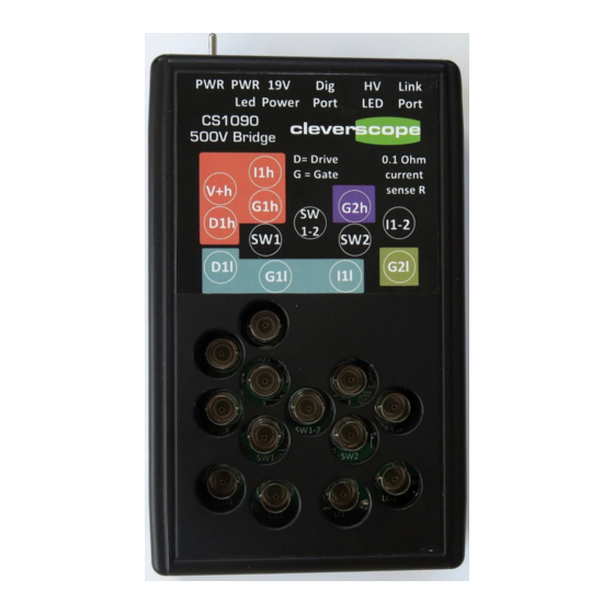
Using the CS1090 500V Bridge
The Power switch is used to turn on the
19V power source. Up is OFF.
A CS448 black digital RJ45 cable can be
plugged into the CS1090 and into the
oscilloscope to display the gate drive
control signals.
When the internal power supply is greater
than 30V the HV Led indicator is on.
The Link port uses a Mini Din 8 plug and
USB adaptor to the PC for control. The
installation for the USB driver and control
program is detailed in a later section.
The two half bridges are labelled 1 and 2
respectively. The SW sockets switch
between 0V and 500V with a rise time of
about 7ns. SW 1-2 is between the two
switching nodes, and switches 500V.
The G1 and G2 sockets are the Gate
Drives, l = low side and h = high side.
I1h probes the high transistor switch
current, and I1l probes the low side
transistor switch current. D1l and D2h
probes the Driver chip. A series resistor of
10 Ohm limits current. The Gate current is
(D1h-G1h)/10. From this gate charge can
be calculated.
1
Cleverscope Ltd
Phone +64 9 524 7456
Mob +64 21 1777 367
Email support@cleverscope.com
21A Lancing Rd, Sandringham
P.O. Box 26-527
Auckland 1025
New Zealand
22 Apr 2018 v1.1
www.cleverscope.com
Advertisement

Summary of Contents for Cleverscope CS1090
- Page 1 IMPORTANT: The CS1090 generates lethal voltages. Do not touch any cables or metal during operation. Summary The CS1090 is used to demonstrate the CS448 in use. The CS1090 includes two half bridges with BNC connections to several interesting circuit nodes including the upper and lower gate drives, the two half bridge switched nodes, and an across-bridge connection.
-
Page 2: Installation
Connector and Transistor Schematic The BNC sockets connect as shown: The CS1090 uses Diodes Inc DGD2304 half bridge drivers with typical 290mA high current and 600 mA low current capability to drive Infineon IPD60R3K3C6 FET switches (650V, 4A, 3.3 R , 4.6nC... - Page 3 Function Mini Din +5V , not used Black Pin 2 White Rx into Pin 6 Green Tx out of Pin 7 Make sure the CS448 application is installed, as it provides the run time the CS1090 application relies on. www.cleverscope.com...
- Page 4 Make sure the power switch on the CS1090 is up (off). Make sure no probes are plugged in. Plug the 19V power into CS1090, and then turn on the Power Switch. This should cause a message to be received in the Message received area: If this happens all is good.
- Page 5 Using the CS1090 Turn off the CS1090 power switch and attach the BNC tip adaptors to one green 1x/10x probe and one red 100x probe. You will find the adaptors in the probe accessory bag: Set the green probe to 10x, as shown. Wrap three turns of the probe cable near the plug end around an LF1290 common mode choke, which should have come with the CS448.
- Page 6 Note that the Gate Drive is transitioning between 0 and 500V, so be careful NOT to touch it. On the CS1090 application, slide the Frequency slider down to 1 kHz. You should see the graph below. The A channel should be flat and the B channel gently sloping as the High Side power supply decays under load.
- Page 7 We can see the 500V Chan A signal is slewing at about 55 kV/us, with rise and fall times of around 7ns. The small pulses in Gate Drive plot caused by the Miller (Reverse Transfer) Capacitance injecting charge into the gate as Switch voltage falls. www.cleverscope.com...
- Page 8 The CS448 is a good tool to check for this and verify the gate drive design. We see about 1.7V. The DGD2304 is capable of 600 mA low output current, and this is why the low going injected value is about half as big. www.cleverscope.com...
- Page 9 SW1, which swings between 0V and Vbus. Here we used a Vbus of 150V (the voltage is reduced to limit the inductor current to 100mA peak - the maximum the CS1090 power supply can handle): Observations: ...
- Page 10 2. The switch Voltage rise is now set by V=Ldi/dt, and takes the full 1.1us. 3. Because the slew rate is so much slower we do not see Miller capacitance induced reduction in the gate voltage. www.cleverscope.com...
- Page 11 Notice also that the DGD2304 is operating at maximum current (309 mA), and has a voltage drop of 15-7 = 8V (the green curve), indicating that the DGD2304 high transistor has an effective on resistance of about 8/0.309 = 25.9 ohms. It will be about half that for the low transistor, as it can sink 600mA. www.cleverscope.com...
- Page 12 Finding the right serial port If the CS1090 is not responsive to the CS1090 control program, you may have the wrong serial port. Open Device Manager (Start/Control Panel/Device Manager), and expand Port (COM & LPT). Find the one for Silicon Labs CP210x, and change the serial port to that one.
Need help?
Do you have a question about the CS1090 and is the answer not in the manual?
Questions and answers