
Summary of Contents for FlowLine Thermo-Flo LC80 Series
- Page 1 Thermo‐Flo™ Remote Flow Controller LC80 & LC82 Series Manual Flowline Inc. 10500 Humbolt Street Los Alamitos, CA 90720 Tel: (562) 598‐3015 Fax: (562) 431‐8507 www.flowline.com Rev B MN301530 1 of 14 ...
-
Page 2: Table Of Contents
INTRODUCTION / TABLE OF CONTENTS Step One The general‐purpose flow controller is offered in two configurations for low‐flow pump and process protection. The LC80 Series accepts one flow sensor input and provides one 10A relay for low flow control. The LC82 Series accepts two flow sensor inputs and provides two 10A relays for dual low flow control. Package this flow controller with our liquid or gas flow switch sensors. For field mount installation, add a single or dual controller NEMA box. Features Fail‐Safe relay control of pumps, valves or alarms with a 0 to 60 second delay. Easy setup with LED indicators for sensor(s), power and relay status. 35mm DIN rail mount polypropylene enclosure with removable terminal strips. Invert switch changes relay state from NO to NC without rewiring. AC powered Table of Contents Specifications: ................................. 3 Dimensions:................................ 3 Safety Precautions: .............................. 4 Components: ............................... 4 Make a Fail‐Safe System: .......................... 5 Controller Logic: ............................ 5 Getting Started: ... -
Page 3: Dimensions
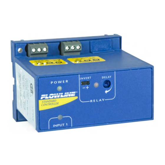
SPECIFICATIONS/DIMENSIONS Step Two Supply voltage: 120 / 240 VAC, 50 ‐ 60 Hz. Top View Consumption: 5 Watts max. Sensor inputs: LC80: (1) flow switch LC82: (2) flow switches Sensor supply: 24 VDC @ 100 mA LED indication: Sensor, power & relay status Contact type: LC80: (1) SPDT Relay LC82: (2) SPDT Relays Contact rating: 250 VAC @ 10A Contact output: Selectable NO or NC Contact delay: 0 to 60 seconds Electronics temp.: F: ‐40°to 158° C: ‐40°to 70° Side View Enclosure rating: 35mm DIN (EN 50 022) Enclosure material: PP (U.L. 94 VO) Fail safety: Power fail‐safe Classification: General purpose Approvals: ... -
Page 4: Safety Precautions
Step Three About This Manual: PLEASE READ THE ENTIRE MANUAL PRIOR TO INSTALLING OR USING THIS PRODUCT. This manual includes information on three different models of Remote Relay Flow Controllers from FLOWLINE: LC80 and LC82 series. Many aspects of installation and use are similar between the three models. Where they differ, the manual will note it. Please refer to the part number on the controller you have purchased as you read. User’s Responsibility for Safety: FLOWLINE manufactures several models of controller, with different ... -
Page 5: Make A Fail-Safe System
In critical applications, redundant backup systems and alarms must be used in addition to the primary system. Such backup systems should use different sensor technologies where possible. While this manual offers some examples and suggestions to help explain the operation of FLOWLINE products, such examples are for information only and are not intended as a complete guide to installing any specific system. Controller Logic: ... -
Page 6: Getting Started
Step Four The LC80 Series may be used with almost any Flowline flow with an N‐channel (ends in “‐_ _ _ 2”) or relay (ends in “‐_ _ _ 5”) output. The relay is a single pole, double throw type; the controlled device can be ... -
Page 7: Electrical
ELECTRICAL Step Five VAC Power Input Wiring: Observe the POWER SUPPLY label on the LC80 series. The label identifies the power requirement (120 or 240 VAC) and the terminal wiring. Note: Polarity does not matter with the AC input terminal. Relay Input Wiring: The relay is a dry‐contact single pole, double throw (SPDT) type rated at 250 VAC, 10 Amps. The relay is designed to switch power on and off to a device. There is no active power within the relay contacts alone. Power must be introduced from secondary source or from the power being used by the controller. Power from a secondary source Power from the same source as the controller The two terminal Normally Open (NO) and Normally Closed (NC) will be used in different applications. Remember that the "normal" state is when the relay coil is de‐... -
Page 8: Installation
WIRING / INSTALLATION Step Six Connecting flow switches to input terminals: There are two types of flow switch outputs from Flowline that are compatible with the LC80 series of controller. The typical/most common flow switches have a relay output (models FT10 ‐ _ _ _ 5 and GT10 ‐ _ _ _ 5) with 4 wires as the output (Red, Black, Green and White). Not as common, Flow Switches with FET outputs (N‐Channel only, models FT10 ‐ _ _ _ 2 and GT10 ‐ _ _ _ 2) with three wires (Red, Black and White) can also be wired to the flow controller. See the illustration below to indicate wiring for your switch and the polarity of the switch output. Note: the Shield wire will be used only for long cable runs or where excessive electrical noise is present. Standard Relay Output Flow Switches FET Switch (N‐Channel*) Flow Switches * P‐Channel FET switches cannot be used with Flow Controller Panel DIN Rail Mounting: The controller may be mounted by either a back panel using two screws through mounting holes located at the corners of the controller or by snapping the controller on 35 mm DIN Rail. Note: Always install the controller in a location where it does not come into contact with liquid. 8 of 14 MN301530 Rev B... -
Page 9: Application Examples
APPLICATION EXAMPLES Step Seven LED Indication: Use LED's located above the input terminals to indicate whether the switch is in a Flow or No‐ Flow state. With the flow switch wired NC, the Amber LED indicates No‐Flow and no LED indicates flow. Wiring the switch NO (reversing the Red and Black wires), the Amber LED indicates Flow and no LED indicates No‐Flow. NC Wiring NC Wiring NO Wiring NO Wiring Amber LED LED OFF Amber LED LED OFF Rev B MN301530 ... -
Page 10: Low Flow Alarm
APPLICATION EXAMPLES Step Seven Low Flow Alarm: The goal is to indicate when the flow rate falls below a certain point. If it does, an alarm is supposed to sound, alerting the operator of a low flow condition. The flow switch is wired to Input 1 and the alarm is wired through Relay 1. If power is accidentally cut to the controller, the sensor's ability to notify the operator of a low flow condition could be lost. The system must alert the operator not only to low flow, but to controller power loss. To do this, connect the hot lead of the alarm to the NC side of the relay terminal of the controller. If power is lost, the relay will be de‐ energized, and the alarm will sound (if there is still power to the alarm ... -
Page 11: Flow Switch Calibration
FLOW SWITCH CALIBRATION Step Eight Set Points: If the preset factory calibration is not adequate for your application, follow the calibration steps listed below. Note: the switch's internal LED will be on when the switch detects no‐flow and will off when the switch detects flow. 1. Install the fitting and flow switch as described in the Installation section of this manual. Turn the flow switch and controller power on and adjust the flow rate to the application setting. If the medium to be sensed is likely to be subject to high temperature variations, the flow switch should be set at the highest normal temperature likely to be encountered. 2. Locate the potentiometer knob at the top of the flow switch. The red LED is visible through the potentiometer. (If the LED is on, slowly adjust the potentiometer ... -
Page 12: Appendix
APPENDIX Step Nine Controller Logic: Please use the following guide to understand the operation of the controllers. 1. Power LED: Make sure the Green power LED is ON when power is supplied to the controller. 2. Input LED: For NC switch wiring, the input LED on the controller will be Amber when the switch reads no‐ flow and OFF when the switch reads flow. 3. Invert Operation: When the input LED turn OFF and ON, the relay LED will also switch. With invert OFF, the relay LED will be ON when the input LED is ON and OFF when the input LED is OFF. With invert ON, the relay LED will be OFF when the input LED is ON and ON when the input LED is OFF 4. Relay Operation: The relay may be wired either NO or NC. The normal state of the relay is when its LED is OFF. With the LED ON, the relay is in the energized mode and all terminal connections are reversed. Troubleshooting: PROBLEM SOLUTION Controller is powered, but nothing First check the Power LED to make sure it is Green. If not, check happens. the wiring, power and make sure the terminal is seated correctly over the 3‐pins. A Flow or No‐Flow condition is Check ... - Page 13 APPENDIX Step Nine Relay Latch Logic (Relay 2, LC82 Series only): This relay is primarily a flow/no‐flow relay. However, when used as a level relay, it can either be an independent relay (high or low level alarm) or a latching relay (automatic fill or empty) with latch ON. With Latch OFF, the relay will only respond to the Input 2A. Input 2B will be ignored. This configuration is ideal for alarming, such as flow, no‐flow, leak detection, ...
-
Page 14: Warranty
WARRANTY, RETURNS AND LIMITAITONS Step Ten Warranty Flowline warrants to the original purchaser of its products that such products will be free from defects in material and workmanship under normal use and service in accordance with instructions furnished by Flowline for a period of two years from the date of manufacture of such products. Flowline's obligation under this ...
Need help?
Do you have a question about the Thermo-Flo LC80 Series and is the answer not in the manual?
Questions and answers