Advertisement
Quick Links
General Guidelines
• It is the user's responsibility to read and follow all instructions.
• Keep these instructions with the product at all times and review before each use.
• It is the responsibility of this product's owner to furnish the instructions to any person that borrows
or purchases the product.
• Inspect the product before use to ensure it is assembled properly and all parts are in safe working
order and free of defects.
• Never modify this product in any way.
• All circumstances cannot be addressed in these instructions. Please use common sense and prac-
tice general safety measures when using this product.
• Parts and/or instructions are subject to change without notice.
Safety
• Do not exceed the rated weight capacity of 500 lbs.
• Always ensure the mower wheels fit properly into the wheel cradles before lifting.
• Secure the mower with tie down straps (sold separately) before lifting.
• Always lock the brake pullers before working on the mower.
• Store the lift in a safe, dry place.
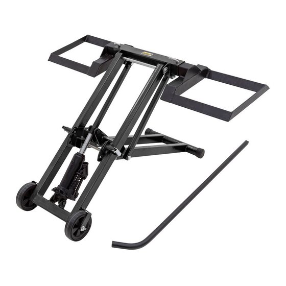
Specifications
Maximum Capacity:
Lift Range:
Maximum Tire Width:
Fit Tire Diameter:
Inner Wheel Tread:
Outer Wheel Tread:
Rev. 021820
Lawn Mower Lift
Instructions for Part # HML-05
500 lbs.
0-24 in.
10.5 in.
10-17 in.
18.5-26 in.
40-47.6 in.
1-888-651-3431
Page 1
Advertisement

Related Manuals for Guardian HML-05


Summary of Contents for Guardian HML-05
- Page 1 Lawn Mower Lift Instructions for Part # HML-05 General Guidelines • It is the user’s responsibility to read and follow all instructions. • Keep these instructions with the product at all times and review before each use. • It is the responsibility of this product’s owner to furnish the instructions to any person that borrows or purchases the product.
-
Page 2: Diagram & Parts List
Diagram & Parts List NO. Description QTY. Description QTY. Cradle Lock Pin M10x55 Brake Pin Top Frame Spring Cradle Medium Axle Handle Bottom Axle Lock Nut M10 Caster Top Axle Hex Nut M10 Small R-Pin 1.5mm Bottom Frame M12 Washer Front Cap Lift Arm Cylinder Pin M12x40... - Page 3 Assembly This item will be mostly assembled out of the box. 1. Pull out the lift and place it on solid flat ground. Insert the bottom axle (18) into the lift as the dia- gram shows (may already installed). Add the two casters (19) on both sides of the axle and lock in place with washers (27) and R-pins (7).
- Page 4 Lifting 1. Pull out (unlock) the brake puller (13) of the safety device Lifting on both sides of the lift. 2. Lower the lift by releasing the wing nut on the jack with the notched end of the handle (4); put some weight on the cradles if needed.
- Page 5 Product Warranty and Liability GENERAL PRODUCT WARRANTY: Products purchased from the Authorized Dealer (original place of purchase) or Merchant (“Dealer”) will be free of defects in material and workmanship at the time of receipt, and will meet the specifications stated at the place of purchase transaction or online at the Dealer’s website, under normal use and service when correctly installed, operated and maintained.
Need help?
Do you have a question about the HML-05 and is the answer not in the manual?
Questions and answers