
Summary of Contents for MasterForce 2602007
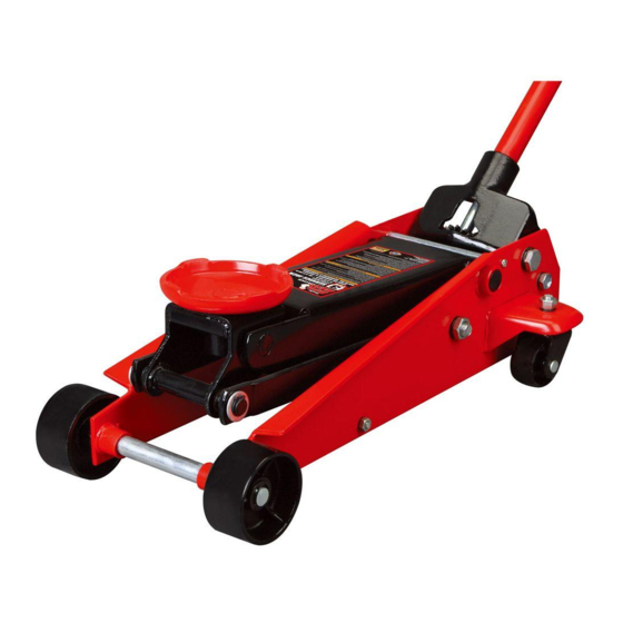
- Page 1 3 Ton Heavy-Duty Floor Jack 260-2007 OPERATOR’S MANUAL CAUTION: To Reduce The Risk Of Injury, User Must Read And Understand Operator’s Manual. Save These Instructions For Future Reference.
-
Page 2: Table Of Contents
TABLE OF CONTENTS Safety Symbols ...................Page 2 Intended Use..................Page 2 Technical Specifications..............Page 2 General Safety Rules................Page 3 Safety....................Page 4 Safety Markings...................Page 4 General Safety Instructions..............Page 5 Assembly....................Page 6 System Air Purge Procedure..............Page 7 Operation....................Page 7 Maintenance Instructions..............Page 8 Assembly Diagram................Page 9-10 Troubleshooting.................Page 11 Notes....................Page 12 Warranty.....................Page 13... -
Page 3: Safety Symbols
SAFETY SYMBOLS Some of the following symbols may be used on your tool. Please study them and learn their meaning. proper interpretation of these symbols will allow you to operate the tool better and safer. Symbol Name Designation / Explanation Pounds Weight Read the operator’s... -
Page 4: General Safety Rules
GENERAL SAFETY RULES WARNING: Read and understand all instructions. Failure to follow all instructions listed below may result in serious injury. CAUTION: Do not allow persons to operate or assemble this jack until they have read this manual and have developed a thorough understanding of how the jack works. WARNING: The warnings, cautions and instructions discussed in this instruction manual cannot cover all possible conditions or situations that could occur. -
Page 5: Safety
SAFETY SAFETY Always follow safety precautions when installing and operating this jack. Keep all decals on the unit clean and visible. Before proceeding ensure that you fully understand and comprehend the full contents of this manual. Failure to operate this equipment as directed may cause injury or death. The distributor is not responsible for any damages or injury caused by improper use or neglect. -
Page 6: General Safety Instructions
GENERAL SAFETY INSTRUCTIONS Position the Jack Position the jack to only lift on the areas of the vehicle as specified by the vehicle manufacturer. Always Use Jack Stands After lifting the vehicle always support the load with appropriately rated vehicle Jack stands before working on the vehicle. -
Page 7: Assembly
ASSEMBLY 1. Familiarize yourself with the jack. 3. Refer to picture below when performing assembling handle sections. Press Quick Lifting Arm Disconnect on handle piece 2, this will allow Saddle slide handle pieces 1 and 2 to connect, align the holes on both sections to allow quick Front disconnect to trigger. -
Page 8: System Air Purge Procedure
SYSTEM AIR PURGE PROCEDURE IMPORTANT: BEFORE FIRST USE Perform the following System Air Purge Procedure to remove any air that may have been introduced into the hydraulic system as a result of product shipment and handling. This step is to be completed without any weight on the jack. -
Page 9: Maintenance Instructions
MAINTENANCE INSTRUCTIONS If you use and maintain your equipment Rust Prevention: properly, it will give you many years of service. Check rams and pump plungers on the power Follow the maintenance instructions carefully unit assemblies daily for any signs of rust or to keep your equipment in good working corrosion. -
Page 10: Assembly Diagram
ASSEMBLY DIAGRAM Page 9... - Page 11 ASSEMBLY DIAGRAM Description Item Part# T830008.5 Power unit assembly T830008.5.1(ASM) Universal joint assembly GB308-6 Steel ball bearing Ø6mm T815016L.3-13(ASM) Oil plug Cotter pin Ø4x60mm Coupling connector C-clip Ø30mm Oil cup M6 GB1152-M6 T830021-3 Saddle pad T83508-10 Pin for saddle Saddle T830008-7 Lifting arm assembly GB894.1-18...
-
Page 12: Troubleshooting
TROUBLESHOOTING Jack will Jack will Jack will Poor jack Will not lift to not lift not hold Causes and Solutions not lower lifting full extension load load Release valve is not completely closed (Turn handle clockwise). Weight Capacity Exceeded. Air is in the hydraulics. Purge air from system. -
Page 13: Notes
NOTES Page 12... -
Page 14: Warranty
90-DAY MONEY BACK GUARANTEE This MASTERFORCE™ brand prouduct carries our 90-Day Money Back Guarantee. If you are not completely satisfied with your MASTERFORCE™ brand prouduct for any reason within ninety (90) days from the date of purchase, return the tool with your original receipt to any MENARDS®... - Page 16 © 2010 Menard, Inc., Eau Claire, WI 54703 08/2019...
Need help?
Do you have a question about the 2602007 and is the answer not in the manual?
Questions and answers