Advertisement
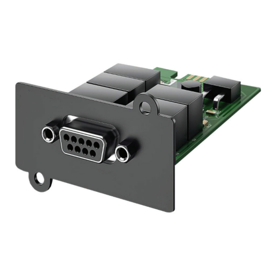
1. The Relay Control Card is pre-installed in the UPS and the DB9 connector is pre-wired to the diagram below.
2. Using the diagram as a guide, wire in the connections to your monitoring device.
3. Plug the DB9 connector into the Relay Control Card.
4. Plug the supplied power adapter into an open outlet on the UPS.
PIN 5
Made in the USA
3 Year Warranty
PIN 1
PIN 2
PIN 7
Pin Assignment
Pin1
Pin2
Pin5
Pin7
Pin9
N56W24720 N. Corporate Circle • Sussex, WI 53089
800-451-1460 • www.rathcommunications.com
Relay Control Card
Part #: 2500-LUPSM
PIN 9
Function
UPS Fault
Summary Alarm
Common (For Relays)
Battery Low
Utility Line Fail
Installation Guide
Relay Control Card 2500-LUPSM
I/O
O/P
O/P
O/P
O/P
O/P
RP8500LUPSM
Ver. 1
08/20
Advertisement
Table of Contents

Summary of Contents for Rath 2500-LUPSM
- Page 1 Installation Guide Relay Control Card 2500-LUPSM Relay Control Card Part #: 2500-LUPSM 1. The Relay Control Card is pre-installed in the UPS and the DB9 connector is pre-wired to the diagram below. 2. Using the diagram as a guide, wire in the connections to your monitoring device.
- Page 2 Installation Guide Relay Control Card 2500-LUPSM APPENDIX A: Relay Control Card RELAYIO500 Function Description: Status Condition Pin1 Short to Pin5 UPS Fault (Inverter Fault / DC Bus Fault / Over Temperature / Output Short / Battery Over Charge / Battery Test Fail 1 / Fan Error 1)
Need help?
Do you have a question about the 2500-LUPSM and is the answer not in the manual?
Questions and answers