
Summary of Contents for Texas Instruments SLLU040A
- Page 1 2−GBPS Differential Repeater Evaluation Module User’s Guide November 2002 High-Performance Linear/Interface Products SLLU040A...
- Page 2 IMPORTANT NOTICE Texas Instruments Incorporated and its subsidiaries (TI) reserve the right to make corrections, modifications, enhancements, improvements, and other changes to its products and services at any time and to discontinue any product or service without notice. Customers should obtain the latest relevant information before placing orders and should verify that such information is current and complete.
- Page 3 EVM IMPORTANT NOTICE Texas Instruments (TI) provides the enclosed product(s) under the following conditions: This evaluation kit being sold by TI is intended for use for ENGINEERING DEVELOPMENT OR EVALUATION PURPOSES ONLY and is not considered by TI to be fit for commercial use. As such, the goods being provided may not be complete in terms of required design-, marketing-, and/or manufacturing-related protective considerations, including product safety measures typically found in the end product incorporating the goods.
- Page 4 EVM User’s Guide. When placing measurement probes near these devices during operation, please be aware that these devices may be very warm to the touch. Mailing Address: Texas Instruments Post Office Box 655303 Dallas, Texas 75265 Copyright 2002, Texas Instruments Incorporated...
- Page 5 Information About Cautions and Warnings Preface Read This First About This Manual This EVM user’s guide provides information about the 2-GBPS differential repeater evaluation module. How to Use This Manual This document contains the following chapters: Chapter 1 — Introduction Chapter2 —...
- Page 6 Related Documentation From Texas Instruments Related Documentation From Texas Instruments To obtain a copy of any of the following TI document, call the Texas Instruments Literature Response Center at (800) 477-8924 or the Product Information Center (PIC) at (972) 644-5580. When ordering, identify this booklet by its title and literature number.
-
Page 7: Table Of Contents
Contents Contents Introduction ..............Overview . - Page 8 Contents viii...
-
Page 9: Introduction
Chapter 1 Introduction The 2-GBPS differential repeater evaluation module (EVM) allows evaluation of the SN65LVDS100, SN65LVDS101, and SN65CML100 differential repeaters/ translators. This user’s guide gives a brief overview of the EVM, setup and operation instructions, and typical test results that can be expected. Topic Page Overview... -
Page 10: Overview
Overview 1.1 Overview The 2-GBPS differential repeater evaluation module (EVM) is designed for evaluation of the SN65LVDS100, SN65LVDS101, and SN65CML100 differential repeaters/ translators. The SN65LVDS100 and SN65LVDS101 devices both incorporate wide common-mode range receivers, allowing receipt of LVDS, LVPECL, or CML input signals. The SN65LVDS100 provides an LVDS output, the SN65LVDS101 incorporates an LVPECL output driver, and the SN65CML100 delivers a CML output. -
Page 11: Signal Paths
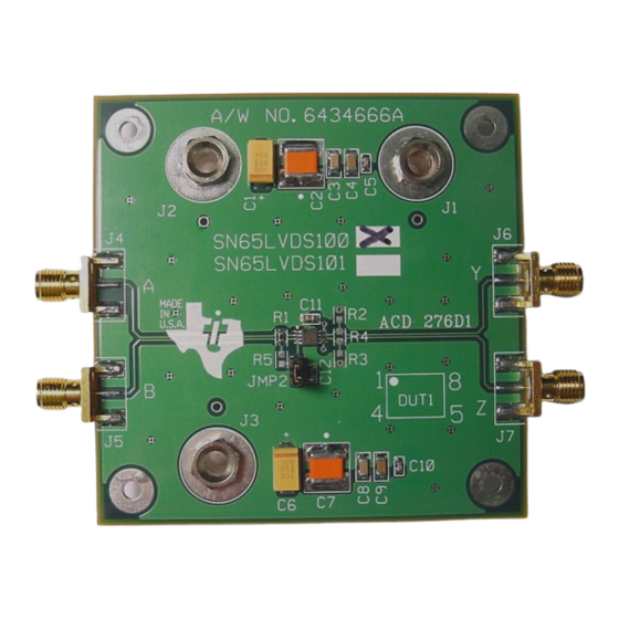
Signal Paths 1.2 Signal Paths A partial schematic of the EVM is shown in Figure 1-2 and a full schematic is in chapter 3. Edge-mount SMA connectors (J4, J5, J6, and J7) are provided for data input and output connections. Three power jacks (J1, J2, and J3) are used to provide power to and a ground reference, for the EVM. -
Page 13: Setup And Equipment Required
Chapter 2 Setup and Equipment Required This chapter examines the setup and use of the evaluation module and the re- sults of operation. Topic Page Overview ........... . . Applying an Input . -
Page 14: Overview
Overview 2.1 Overview LVDS driver output characteristics are specified in the TIA/EIA-644 standard. LVDS drivers nominally provide a 350-mV differential signal, with a 1.25-V offset from ground. These levels are attained when driving a 100-Ω differential line-termination test load (see Figure 2-1). In real applications, there may be a ground potential between a driver and receiver(s). -
Page 15: Applying An Input
Applying an Input Figure 2-2. EVM Power Connections for SN65LVDS100 Evaluation Power Supply 1 3.3V Power Supply 2 1.22V 100 Ω 50 Ω 50 Ω Matched Matched Pattern Cables Cables Generator SMA to SMA SMA to SMA Oscilloscope Warning Power jacks J1, J2, and J3 are not insulated on the backside of the EVM. -
Page 16: External Termination For Differential Cml Or Lvpecl Inputs To Evm
Applying an Input with 50-Ω pullups to V . When using external terminations, the onboard termination resistor R1 should be removed from the EVM. It should be noted that the signal quality at the receiver input may be degraded when external terminations are used, as a significant stub exists from the external termination network to the receiver input. -
Page 17: Observing An Output
Observing an Output Figure 2-4. External Termination for Single-Ended LVPECL Inputs to EVM 50 Ω Signal Source EVM BOARD NOTES: A. Add jumper Jmp2 and 0-Ω R5 B. Remove R1 2.3 Observing an Output Direct connection to an oscilloscope with 50-Ω internal terminations to ground is accomplished without R2, R3, and R4 . -
Page 18: Typical Test Results
Typical Test Results LVPECL drivers need a 50-Ω termination to V . A modification of Figure 2-2 and the above instructions are used when evaluating an SN65LVDS101 with a direct connection to a 50-Ω oscilloscope. With power supply 1 in Figure 2-2 set to 3.3 V, power supply 2 should be set to 1.3 V (2 V below V ) to provide the correct termination voltage. -
Page 19: Typical Output From Sn65Lvds100 Evm
Typical Test Results Figure 2-5. Typical Output From SN65LVDS100 EVM Setup and Equipment Required... -
Page 21: Evm Construction
Chapter 3 EVM Construction This chapter lists the EVM components and examines the construction of the evaluation module. Topic Page Schematic ........... . Bill of Materials . -
Page 22: Schematic
Schematic 3.1 Schematic J1 -1 68 µF 1 µF 0.1 µF 0.001 µF 10 µF J2 -1 10 µF 1 µF 0.1 µF 0.001 µF 68 µF J3 -1 CC01 Uninstalled DUT1 .010 µF R1 100 Ω Uninstalled DUT_MSOP8 CC01 Uninstalled JMP2 Uninstalled... -
Page 23: Bill Of Materials
Bill of Materials 3.2 Bill of Materials ITEM MFG PART NO. REF. DESCRIPTION VALUE OR DES. FUNCTION INSTALLED 35 V, 10%, 10 µF Sprague 293D106X0035D2W C1,C6 Capacitor, SMT, TANT 12063G105ZATRA C3,C8 Capacitor, SMT1206 25 V, 80 -20%, 1.0 µF Capacitor, SMT1206 50 V, 5%, 0.1 µF 12065C104JATMA C4,C9 Sprague... -
Page 24: Board Stackup
Board Stackup 3.3 Board Stackup GENERAL NOTES: UNLESS OTHERWISE SPECIFIED 1. ALL FABRICATION ITEMS MUST MEET OR EXCEED BEST INDUSTRY PRACTICE. IPC-A 600C ( Commercial Std.) 2.LAMINATE MATERIAL: NELCO N4000-13 (DO NOT USE - 13SI) 3. COOPER WEIGHT:1 OZ. START INTERNAL AND 1/2 OZ. START EXTERNAL 4. -
Page 25: Board Layer Patterns
Board Layer Patterns 3.4 Board Layer Patterns (Not to Scale) Layer 1 - Signal/GND Fill (Top Side) Layer 2 - GND Plane (INT1) EVM Construction... - Page 26 Board Layer Patterns Layer 3 - V Split Plane (INT2) Layer 4 - GND Plane (Bottom Side)
- Page 27 Mouser Electronics Authorized Distributor Click to View Pricing, Inventory, Delivery & Lifecycle Information: Texas Instruments SN65LVDS100EVM SN65LVDS101EVM SN65CML100EVM...
Need help?
Do you have a question about the SLLU040A and is the answer not in the manual?
Questions and answers