Table of Contents
Advertisement
Quick Links
Advertisement
Table of Contents

Related Manuals for CHP DPF-300

Summary of Contents for CHP DPF-300
- Page 1 DPF-300 INSTRUCTION MANUAL PATENTED INSTRUCTION MANUAL DPF-300 Page 1 2020.09...
-
Page 2: Table Of Contents
TO BE SEPARATED ............23 11. WARRANTY CONDITIONS ......................... 24 12. TECHNICAL SUPPORT ........................24 DPF-300 DECLARATION OF CONFORMITY ................... 25 WARNING The information contained in this document is subject to change at the discretion of the company without prior notice. -
Page 3: Introduction
Among the features of the DPF-300 is the possibility to change the milling cutter and the INTERCHANGEABLE GUIDE (patented) quickly. -
Page 4: Safety Rules
The machine is built according to the safety criteria dictated by current regulations, indicated in the declaration of conformity attached to this manual. IDENTIFICATION PLATES ON THE MACHINE DPF-300 MACHINE DATA PLATE It is the identification plate of the machine, bearing its main specifications and its Serial Number. -
Page 5: Meaning Of The Warning Plates Affixed To The Machine
DPF-300 INSTRUCTION MANUAL MEANING OF THE WARNING PLATES AFFIXED TO THE MACHINE This symbol on the head baseplate indicates "DO NOT TOUCH" the cutter while it is running. This symbol on the workbench indicates that the machine complies with standard CEI EN 61340-5-1 regarding the protection of electronic devices against electrostatic phenomena. - Page 6 DPF-300 INSTRUCTION MANUAL ATTENTION This plate, located on the front side of the machine, above the workbench, prompts the operator to check the clogging of the suction Check the clogging of the suction filter, constantly. filter constantly. This plate, located on the front of the...
-
Page 7: Machine Description
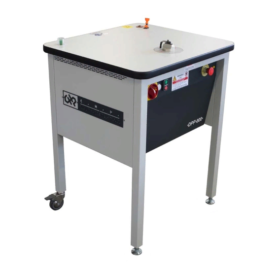
DPF-300 INSTRUCTION MANUAL 2. MACHINE DESCRIPTION The machine (Fig.2) consists of steel frame with an ESD safe workbench on top, on which the milling head (cutter) is installed. The frame is supported by two steel feet and two ESD safe swivel casters with brakes for practical positioning;... - Page 8 DPF-300 INSTRUCTION MANUAL The protective casing fixed with 4 screws on the back of the machine can be removed when carrying out maintenance work on the motor and the extraction system (Fig.3). Under the frame bedplate is a dust filter that features a special built-in filter cartridge, in accordance with EN 60335-269 and can easily be opened using the side clips.
- Page 9 DPF-300 INSTRUCTION MANUAL The milling head consists of a bedplate and a mounting head on which a hardened ground steel inter- changeable guide is installed (Fig.4). The guide features a central slot along which the milling cutter moves. PCB dust is removed through the rear vacuum pipe that is connected to the electric extraction system and the corresponding dust filter;...
-
Page 10: Transport And Storage
Wooden pallet and cardboard box: 90 kg. Wooden crate: 121 kg. Fig. 7 STORAGE CONDITIONS If DPF-300 is not installed immediately after delivery, store the machine in its original packaging, under the following conditions: Non-operating temperature: -10C +50C ▪ Humidity: less than 80%, non-condensing ▪... -
Page 11: Machine Installation
DPF-300 INSTRUCTION MANUAL 4. MACHINE INSTALLATION CAUTION!! The installation of DPF-300 requires a thorough knowledge of the machine and must, therefore, be entrusted only to specially trained personnel. SPACE NEEDED FOR MACHINE OPERATION The drawing below (Fig.8) indicates the minimum space (in millimeter) necessary for the correct operation and maintenance of DPF-300: Fig. -
Page 12: Installation Procedure
DPF-300 INSTRUCTION MANUAL INSTALLATION PROCEDURE The machine comes with all its parts already assembled. Before using the machine, perform the installation steps below: • Adjust the height of the 2 feet making sure that they rest correctly on the ground and secure their position with the locking nuts. -
Page 13: Installing/Replacing The Guide And The Bit
DPF-300 INSTRUCTION MANUAL 5. INSTALLING/REPLACING THE GUIDE AND THE BIT Make sure that the system is disconnected from the power supply before carrying out any maintenance or adjustment work. STAINLESS STEEL SUCTION PIPE INTERCHANGEABLE GUIDE HEAD REFERENCE MARK MILLING REFERENCE MARK Fig. -
Page 14: Using The Machine
DPF-300 INSTRUCTION MANUAL 6. USING THE MACHINE Always wear safety goggles, protective gloves and safety earmuffs when using the machine. Once the machine has been installed correctly (Section 4) and the appropriate interchangeable guide and bit have been inserted (Section 5), the machine can be operated from the front control panel Fig.10. -
Page 15: Operational Phases
DPF-300 INSTRUCTION MANUAL OPERATIONAL PHASES The sequence of figures below indicates how to use the machine correctly. 1. Position the slot of the PCB and insert PCB into the guide rail until it rests on the guide. SLOT ISTHMUS GUIDE... -
Page 16: Pcb Orientation
DPF-300 INSTRUCTION MANUAL PCB ORIENTATION Figures below indicate the correct orientation of the PCB in relation to the reference axis of the interchangeable guide, for the correct operation of the machine: CORRECT INCORRECT Fig. 15 CORRECT INCORRECT Fig. 16 Reference axis Page 16 2020.09... -
Page 17: Enviromental Impact
DPF-300 INSTRUCTION MANUAL 7. ENVIROMENTAL IMPACT The environmental impact of DPF-300 is minimal and has the following main characteristics: Dust pollution: the machine produces cutting dust that is collected by a special filter provided with a special filter cartridge. Oil pollution: the machine does not use and, therefore, does not release oil into the environment. -
Page 18: Wiring Diagram
DPF-300 INSTRUCTION MANUAL 8. WIRING DIAGRAM Page 18 2020.09... -
Page 19: Machine Maintenance
DPF-300 INSTRUCTION MANUAL 9. MACHINE MAINTENANCE Make sure that the system is disconnected from the power supply before carrying out any maintenance or adjustment work. The machine is designed to allow easy maintenance; therefore, the electrical panel can be accessed from the front of the machine, via the protective casing that consists of a hinged door secured with the 3 screws indicated by the arrows (Fig.17). -
Page 20: Routine Maintenance
- FR4 milling bit (10pc. Pack) available standard diameters 1.5-2.5 mm. P/N DPF-FF-X.X - ALUMINIUM milling bit (10pc. Pack) standard available 1.5-2.5 mm. P/N DPF-FA-X.X - Motor spindle with centring kit P/N DPF-300-TF-000 - Filter cartridge for 1-1/4" filter P/N DPF-CAR-3.0 - Suction kit with regulator P/N DPF-21192-41489 - Suction hose Ø10 P/N DPF-PVCRTAGE010... -
Page 21: Dust Filter Cleaning
DPF-300 INSTRUCTION MANUAL DUST FILTER CLEANING Always wear a dust mask and protective gloves when opening and cleaning the dust container. CLIP CLIP FILTER Fig. 19 CONTAINER The dust filter is located under the frame's rear compartment; it is suitably built and features a filter cartridge that complies with standard EN 60335-269 and can be easily accessed thanks to its special opening system. -
Page 22: Motor Spindle Maintenance
DPF-300 INSTRUCTION MANUAL MOTOR SPINDLE MAINTENANCE Make sure that the system is disconnected from the power supply before carrying out any maintenance or adjustment work. To access the motor spindle, open the electrical panel following the instructions in chap.9. Then remove the 4 screws shown in Fig.20, that secure the protective casing, to access the motor spindle mount. -
Page 23: Technical Specifications
DPF-300 INSTRUCTION MANUAL 10. TECHNICAL SPECIFICATIONS 10.1 GENERAL CHARACTERISTICS Approx. dimensions 64 cm (W) x 70 cm (L) x 95 cm (H) Clearance 164 cm (W) x 170 cm (L) Interchangeable guide material Hardened ground steel Interchangeable guide thickness Standard 1.5 – 2.5 mm Cutter diameter Standard 1.5 –... -
Page 24: Warranty Conditions
INSTRUCTION MANUAL 11. WARRANTY CONDITIONS American Hakko Products, Inc. warrants that CHP DPF-300 will be free from defects in material and workmanship for a period of ninety (90) days from the date of purchase, with extended warranty on electronic portion of the unit, provided that no warranty shall apply to products that have been damaged, altered, abused, improperly installed, improperly maintained, repaired after purchase, or have had their identification markings removed or altered in any way. -
Page 25: Dpf-300 Declaration Of Conformity
EN 61000-6-4 Part 6-4: Generic standards - Emission standard for industrial environments. EN 61000-6-2 Part 6-2: Generic standards - immunity for industrial environments. DIRECTIVE 2014/35/UE (Low Voltage) All electrical materials and subsystems used in the construction of the DPF-300 machine comply with Directive 2014/35 /UE. July 15th, 2020 Page 25 2020.09... - Page 26 DPF-300 INSTRUCTION MANUAL NOTES: Page 26 2020.09...
Need help?
Do you have a question about the DPF-300 and is the answer not in the manual?
Questions and answers