Table of Contents
Advertisement
Quick Links
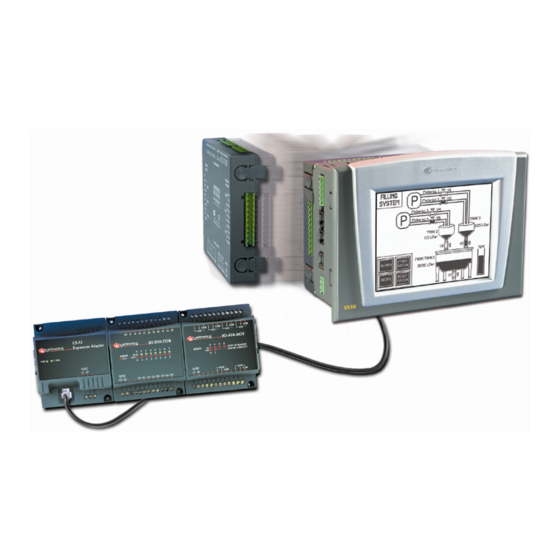
Vision™ OPLC™
This guide provides basic information for Unitronics' controller V530-53-B20B.
General Description
V530 OPLCs are programmable logic controllers that comprise a built-in operating panel containing a
monochrome touchscreen, which displays a virtual keyboard when the application requires the
operator to enter data.
Communications
I/O Options
Information
Mode
Programming
Software,
& Utilities
Data Tables
Additional product documentation is in the Technical Library, located at www.unitronics.com.
Technical support is available at the site, and from support@unitronics.com.
Unitronics
2 serial ports: RS232 (COM 1), RS232/485 (COM 2)
1 CANbus port
The user can order and install an additional port. Available port types
are: RS232/RS485, and Ethernet
Communication Function Blocks include: SMS, GPRS, MODBUS
serial/IP Protocol FB enables PLC to communicate with almost any
external device, via serial or Ethernet communications
V530 supports digital, high-speed, analog,
weight and temperature measurement I/Os
via:
Snap-in I/O Modules
Plug into the back of the controller to
provide an on-board I/O configuration
I/O Expansion Modules
Local or remote I/Os may be added via
expansion port or CANbus
Installation instructions and other data may be found in the module's technical
specification sheet.
This mode enables you to:
View & Edit operand values, COM port settings, RTC and screen
contrast/brightness settings
Calibrate the touchscreen
Stop, initialize, and reset the PLC
To enter Information Mode, press the <i> button for several seconds.
The Unitronics Setup CD contains VisiLogic software and other utilities
VisiLogic
Easily configure hardware and write both HMI and Ladder control
applications; the Function Block library simplifies complex tasks such
as PID. Write your application, and then download it to the controller
via the programming cable included in the kit.
Utilities
Includes UniOPC server, Remote Access for remote programming
and diagnostics, and DataXport for run-time data logging.
To learn how to use and program the controller, as well as use utilities such as
Remote Access, refer to the VisiLogic Help system.
Data tables enable you to set recipe parameters and create datalogs.
Installation Guide
V530-53-B20B
1
Advertisement
Table of Contents

Related Manuals for Klinkmann Unitronics Vision V530-53-B20B


Summary of Contents for Klinkmann Unitronics Vision V530-53-B20B
- Page 1 Vision™ OPLC™ Installation Guide V530-53-B20B This guide provides basic information for Unitronics’ controller V530-53-B20B. General Description V530 OPLCs are programmable logic controllers that comprise a built-in operating panel containing a monochrome touchscreen, which displays a virtual keyboard when the application requires the operator to enter data.
-
Page 2: Danger Symbols
Vision™ OPLC™ V530-53-B20B Standard Kit Contents Vision controller Battery (not installed) 3 pin power supply connector Programming cable + RS232 adapter 5 pin CANbus connector Mounting brackets (x4) CANbus network termination resistor Rubber seal Unitronics’ Setup CD Danger Symbols When any of the following symbols appear, read the associated information carefully. Symbol Meaning Description... -
Page 3: Inserting The Battery
Installation Guide Inserting the Battery In order to preserve data in case of power-off, you must insert the battery. The battery is supplied taped to the battery cover on the rear of the controller. 1. Remove the battery cover shown on page 4. The polarity (+) is marked on the battery holder and on the battery. -
Page 4: Panel Mounting
Vision™ OPLC™ V530-53-B20B Panel Mounting Before you begin, note that the mounting panel cannot be more than 5 mm thick. 1. Make a panel cut-out according to the dimensions in the figure to the right. 2. Slide the controller into the cut- out, ensuring that the rubber seal is in place. -
Page 5: Wiring Procedure
Installation Guide Wiring Do not touch live wires. Install an external circuit breaker. Guard against short-circuiting in external wiring. Use appropriate circuit protection devices. Unused pins should not be connected. Ignoring this directive may damage the device. Double-check all wiring before turning on the power supply. To avoid damaging the wire, do not exceed a maximum torque of 0.5 N·m (5 kgf·cm). -
Page 6: Communication Ports
Vision™ OPLC™ V530-53-B20B Communication Ports Turn off power before changing communication settings or connections. Signals are related to the controller’s 0V; the same 0V is used by the power supply. Always use the appropriate port adapters. Caution The serial ports are not isolated. If the controller is used with a non-isolated external device, avoid potential voltage that exceeds ±... - Page 7 Installation Guide RS232 to RS485: Changing Jumper Settings The port is set to RS232 by factory default. To change the settings, first remove the Snap-in I/O Module, if one is installed, and then set the jumpers according to the following table. Before you begin, touch a grounded object to discharge any electrostatic charge.
- Page 8 Vision™ OPLC™ V530-53-B20B Unitronics...
- Page 9 Helsinki St. Petersburg Moscow tel. +358 9 540 4940 tel. +7 812 327 3752 tel. +7 495 641 1616 automation@klinkmann.fi klinkmann@klinkmann.spb.ru moscow@klinkmann.spb.ru Yekaterinburg Samara Кiev tel. +7 343 287 19 19 tel. +7 846 273 95 85 tel. +38 044 495 33 40 yekaterinburg@klinkmann.spb.ru...
Need help?
Do you have a question about the Unitronics Vision V530-53-B20B and is the answer not in the manual?
Questions and answers