
Summary of Contents for Air Design PREMA Series
- Page 1 INSTALLATION & MAINTENANCE INSTRUCTIONS PREMA CEILING VOID ENERGY RECOVERY VENTILATION UNITS THESE INSTRUCTIONS MUST BE READ FULLY BEFORE COMMENCING INSTALLATION. REF: AD PREMA INST ISSUE A: 12.09.17...
-
Page 2: Table Of Contents
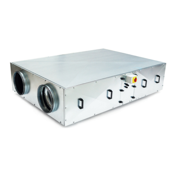
INSTALLATION & MAINTENANCE INSTRUCTIONS PREMA CEILING VOID ENERGY RECOVERY VENTILATION UNITS Contents Page Installation, Operating & Maintenance Instructions Introduction, general, delivery, safety, warnings and labels, other risks Maintenance regulations, disassembly and re-assembly, disposal, handling and offloading, storage Equipment start-up, installation and assembly Unit dimensions Unit outline Minimum space required for maintenance... - Page 3 INSTALLATION & MAINTENANCE INSTRUCTIONS PREMA CEILING VOID ENERGY RECOVERY VENTILATION UNITS Introduction The information contained in this document provides details of installation, operation and maintenance for installers and users. The PREMA ceiling void energy recovery ventilation range comprises a combination of high efficiency centrifugal fans with EC motors, a counter flow design plate heat exchanger and a casing with acoustic treatment.
-
Page 4: Maintenance Regulations, Disassembly And Re-Assembly, Disposal, Handling And Offloading, Storage
Technical Literature, and/or project specific documentation Directive 2006/42/CE. The associated directive handbook contains information and advice for all responsible personnel and is designed General to minimise possible risks of personal injury or damage to property. INSTALLATION & MAINTENANCE INSTRUCTIONS All maintenance procedures shall only be carried out whilst the product is isolated from electrical supplies. -
Page 5: Equipment Start-Up, Installation And Assembly
INSTALLATION & MAINTENANCE INSTRUCTIONS PREMA CEILING VOID ENERGY RECOVERY VENTILATION UNITS Equipment Start-Up Before operating the following checks must be made: • Ensure that inlet / outlet connections are free from obstruction • Check that all product components are securely fastened in their associated sealing gaskets •... -
Page 6: Unit Dimensions
INSTALLATION & MAINTENANCE INSTRUCTIONS PREMA CEILING VOID ENERGY RECOVERY VENTILATION UNITS Unit Dimensions Control Box on PREMA180 only Side View Isolator ØD ØD Ø13.7 E crs Condensate Drain End View Top Plan View Product Weight kg PREMA180 1537 PREMA330 1914 1286 PREMA540 2066... -
Page 7: Unit Outline
INSTALLATION & MAINTENANCE INSTRUCTIONS PREMA CEILING VOID ENERGY RECOVERY VENTILATION UNITS PERMA Installation, Operating & Maintenance PERMA Installation, Operating & Maintenance UNIT Outline Unit Outline Note: These units must be mounted and be fully levelled in the horizontal plane. UNIT Outline Note: These units must be mounted and be fully levelled in the horizontal plane. -
Page 8: Minimum Space Required For Maintenance
PERMA INSTALLATION & MAINTENANCE INSTRUCTIONS Installation, Operating & Maintenance Exhaust Supply PREMA CEILING VOID ENERGY RECOVERY VENTILATION UNITS Minimum Maintenance space and Condensation Removal Supply Extract Filters Filters 550mm Width Minimum Space Required for Maintenance Minimum MINIMUM space required for maintenance Condensation Removal Access into the equipment is via access panels located on proper functioning both sides of the unit. -
Page 9: Condensation Removal
INSTALLATION & MAINTENANCE INSTRUCTIONS PERMA PREMA CEILING VOID ENERGY RECOVERY VENTILATION UNITS nance space and Condensation Removal Condensation Removal Condensation removal is essential for the proper functioning of the energy recovery unit. ired for maintenance Condensation Removal The unit is equipped with a condensate drainage point with an outside diameter of Ø13.7mm (¼” MDP), terminating t is via access panels located on Condensation Removal is essential for the proper functioning approximately 50mm from the panel. - Page 10 INSTALLATION & MAINTENANCE INSTRUCTIONS PREMA CEILING VOID ENERGY RECOVERY VENTILATION UNITS Controls The controller software is designed to handle four different applications. Each application has its own set of parameters (input value range, set points, p-band, min and max speeds, etc.) and control function. The application is pre-selected when manufactured but can be changed like the other parameters using the CTRL-DSP.
-
Page 11: Ctrl-Dsp Display
Duct air pressure (Control input signal 0-10VDC mapped to pressure sensor range) is controlled by a PID controller (Proportional, Integrating and Derivating). High pressure value gives low fan speed INSTALLATION & MAINTENANCE INSTRUCTIONS Manual fan speed control PREMA CEILING VOID ENERGY RECOVERY VENTILATION UNITS The fan speed is set manually using the CTRL-DSP’s UP and DOWN buttons (resolution 1%). -
Page 12: Display Functions
INSTALLATION & MAINTENANCE INSTRUCTIONS PREMA CEILING VOID ENERGY RECOVERY VENTILATION UNITS Display Functions to select required menu Press OK to enter any parameter P02 to P04 only visible in selected applications Pressure or CO P12 only visible if P11 set to ‘Pre’ or ‘Post’ heating type Main Menu Language Date / Time... -
Page 13: Main Menu Functions
INSTALLATION & MAINTENANCE INSTRUCTIONS PREMA CEILING VOID ENERGY RECOVERY VENTILATION UNITS Main Menu Functions Allows selection of language between English and Italian* Main Menu Press OK to enter Language Language is flashing: use to choose Press OK to select *The factory setting (DEFAULT) is English Allows selection of date and time Main Menu Press OK to enter... - Page 14 INSTALLATION & MAINTENANCE INSTRUCTIONS PREMA CEILING VOID ENERGY RECOVERY VENTILATION UNITS Parameter is not visible when application is MANUAL or 0-10V Main Menu Allows selection of desired maximum sensor value P02: Sensor Range MIN Press OK to enter Value is flashing: use to choose Press OK to select Available settings are:...
- Page 15 INSTALLATION & MAINTENANCE INSTRUCTIONS PREMA CEILING VOID ENERGY RECOVERY VENTILATION UNITS Allows selection of PID response Main Menu Press OK to enter P05: PID Control PID mode is flashing: use to choose PID Modes available: SLOW: Global gain set to 0.2, other PID values default NORMAL: Global gain set to 0.5, other PID values default FAST: Global gain set to 0.9, other PID values default CUSTOM: Custom is automatically selected if advanced settings in service...
- Page 16 INSTALLATION & MAINTENANCE INSTRUCTIONS PREMA CEILING VOID ENERGY RECOVERY VENTILATION UNITS Allows adjustment of the minimum fan speed value Main Menu Press OK to enter P08: Min Fan Speed Value is flashing: use to choose Press OK to select Available settings are: Min Value Unit Default...
- Page 17 INSTALLATION & MAINTENANCE INSTRUCTIONS PREMA CEILING VOID ENERGY RECOVERY VENTILATION UNITS Parameter is only visible when application P11 is set to PRE or POST Main Menu Allows adjustment of the Heating Threshold value P12: Heating Threshold Press OK to enter Value is flashing: use to choose Press OK to select...
- Page 18 INSTALLATION & MAINTENANCE INSTRUCTIONS PREMA CEILING VOID ENERGY RECOVERY VENTILATION UNITS Summer Cooling Main Menu Allows adjustment of the Min Free Cooling Temperature value P15: Min Free Cooling Temp Press OK to enter Value is flashing: use to choose Press OK to select Available settings are: Min Value Unit...
- Page 19 INSTALLATION & MAINTENANCE INSTRUCTIONS PREMA CEILING VOID ENERGY RECOVERY VENTILATION UNITS Provides a count of number of unit working hours. This value cannot be Main Menu changed. The data is saved both on the CTRL-DSP and the PCB Press OK to enter Working Hours Counter Press OK / ESC to return to main menu Allows saving the setting of parameters in the internal memory of the...
- Page 20 Main Menu Shows the internal functional parameters of the unit. Main Menu Shows the internal functional parameters of the unit. INSTALLATION & MAINTENANCE INSTRUCTIONS Press OK to enter. Press OK to enter. Debug Page Debug Page Press ESC to go back to the previous menu. Press ESC to go back to the previous menu.
-
Page 21: Service Menu Functions
INSTALLATION & MAINTENANCE INSTRUCTIONS PREMA CEILING VOID ENERGY RECOVERY VENTILATION UNITS Service Menu Functions Service Menu on CTRL-DSP To enter the main menu press OK for 3 seconds To exit the main menu press ESC or wait approx. 60 seconds Service Menu S01: Parameter Summary S02: Fan Status Signal... - Page 22 INSTALLATION & MAINTENANCE INSTRUCTIONS PREMA CEILING VOID ENERGY RECOVERY VENTILATION UNITS Allows adjustment of the proportional band for applications to be Service Menu fine-tuned / adjusted beyond P05 Press OK to enter S04: Proportional Band Value is flashing: use to choose Press OK to select Any change from default setting will drive P05 to CUSTOM Available settings are:...
- Page 23 INSTALLATION & MAINTENANCE INSTRUCTIONS PREMA CEILING VOID ENERGY RECOVERY VENTILATION UNITS Shows the internal control parameters of the unit Service Menu Press OK to enter Control Debug Page Press ESC to go back to the previous menu Selected Application (e.g. temperature) Setpoint (e.g.
-
Page 24: Installation Wiring
PERMA Installation, Operating & Maintenance PERMA INSTALLATION & MAINTENANCE INSTRUCTIONS INSTALLATION - WIRING Installation, Operating & Maintenance PERMA PREMA CEILING VOID ENERGY RECOVERY VENTILATION UNITS Installation, Operating & Maintenance INSTALLATION - WIRING All units are Single Phase 220V to 240V 50/60Hz. Mains must be wired directly into the 2P Single Phase INSTALLATION - WIRING Isolator. -
Page 25: Control Board Connections, Power Supply Connections, Sensors
INSTALLATION & MAINTENANCE INSTRUCTIONS PREMA CEILING VOID ENERGY RECOVERY VENTILATION UNITS PERMA Installation, Operating & Maintenance Controls Board Connections PERMA Controls Board Connections Installation, Operating & Maintenance Controls Board Connections PERMA Installation, Operating & Maintenance Controls Board Connections Figure 1 - Motherboard layout Figure 1 - Motherboard Layout Figure 1 - Motherboard layout Power supply connections... -
Page 26: Fault Diagnostics
INSTALLATION & MAINTENANCE INSTRUCTIONS PREMA CEILING VOID ENERGY RECOVERY VENTILATION UNITS Fault Diagnostics In the event of a fault, Exx error code shows on user display. Error Description E000 No connection between CTRL-DSP and motherboard E001 No rotation of fan 1 (supply) E002 No rotation of fan 2 (extract) E003... -
Page 27: Installation, Fitting And Maintenance Instructions For Cylindrical Silencers
Installation, fitting and Maintenance Instruction Electric PRE/POST-heater battery INSTALLATION & MAINTENANCE INSTRUCTIONS The electric heater battery is usually for preventing frost PREMA CEILING VOID ENERGY RECOVERY VENTILATION UNITS damage to the heat exchanger and or, to bring the temperature up to its minimum operating level. Fitting Installation, Fitting and Maintenance Instructions for Ducted Electric PRE / POST-heater The pre-heater is a stand-alone electric heater battery device,... -
Page 28: Filter Dirty Indication, Maintenance
to the duct that is to be attached. Spigotted range of cylindrical silencers should be PERMA attached by sliding a fast clamp connector over rubber INSTALLATION & MAINTENANCE INSTRUCTIONS Installation, Operating & Maintenance seals on spigot and silencer spigot and tightening the PREMA CEILING VOID ENERGY RECOVERY VENTILATION UNITS bolts. -
Page 29: Filter Replacement
INSTALLATION & MAINTENANCE INSTRUCTIONS PREMA CEILING VOID ENERGY RECOVERY VENTILATION UNITS Maintenance: Filter Replacement (Side Access) Filter pressure switches or indicators have been fitted and should be set or adjusted to reflect the commissioned system PERMA Installation, Operating & Maintenance operation. -
Page 30: Service
INSTALLATION & MAINTENANCE INSTRUCTIONS PREMA CEILING VOID ENERGY RECOVERY VENTILATION UNITS Service In order to maximise the useful life of the equipment and keep it operating in good order, the maintenance checks and tasks detailed in these instructions should be performed as part of a regular and routine service schedule. Under normal operating conditions, the following schedule is recommended: Frequency Maintenance Item... -
Page 31: Trouble Shooting
INSTALLATION & MAINTENANCE INSTRUCTIONS PREMA CEILING VOID ENERGY RECOVERY VENTILATION UNITS Condensate Drip Trays and Drains Drain lines should be checked to ensure that they are unobstructed, free draining and free from debris. They should be periodically flushed out and chemically treated as necessary to remove any contamination. Fans EC fan motors operate from a permanent mains power supply;... -
Page 32: Ec Declaration Of Incorporation
EU Declaration of Incorporation Herewith we declare that the air movement equipment below, on the basis of its design and construction in the form brought onto the market is in accordance within the relevant health and safety requirements of the EC Directive for use of machinery. In accordance with the Machinery Directive 2006/42/EC Designation of Equipment: Prema 180, 330, 540 &... - Page 33 INSTALLATION & MAINTENANCE INSTRUCTIONS PREMA CEILING VOID ENERGY RECOVERY VENTILATION UNITS Notes +44 (0)1384 720460 | +44 (0)1384 456337 | SALES@AIR-DESIGN.COM | AIR-DESIGN.COM...
- Page 34 INSTALLATION & MAINTENANCE INSTRUCTIONS PREMA CEILING VOID ENERGY RECOVERY VENTILATION UNITS Notes...
- Page 35 INSTALLATION & MAINTENANCE INSTRUCTIONS PREMA CEILING VOID ENERGY RECOVERY VENTILATION UNITS Notes +44 (0)1384 275800 | +44 (0)1384 275810 | SALES@AIR-DESIGN.COM | AIR-DESIGN.COM...
- Page 36 +44 (0)1384 275800 +44 (0)1384 275810 SALES@AIR-DESIGN.COM AIR-DESIGN.COM 46 THIRD AVENUE | PENSNETT TRADING ESTATE KINGSWINFORD | WEST MIDLANDS | DY6 7US | UK...
Need help?
Do you have a question about the PREMA Series and is the answer not in the manual?
Questions and answers