Table of Contents
Advertisement
Quick Links
9201-B San Mateo Blvd N.E.
Albuquerque, New Mexico 87113 U.S.A. CAGE: 6PC31
U.S.A.
CAGE: 6PC31
Telephone: 1 - 855-250-7027 (Toll Free U.S.A./Canada)
Telephone: 1-505-903-6148 (International Direct)
Website:
www.bendixking.com/support
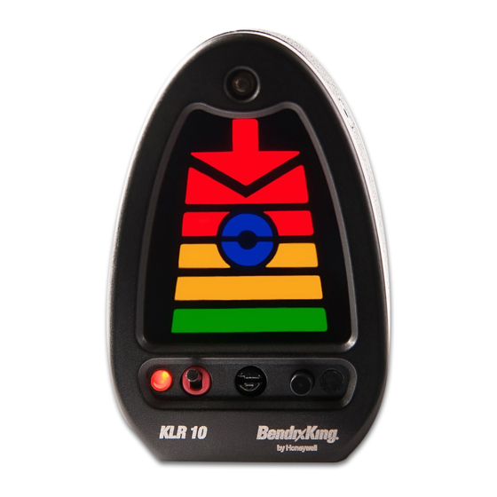
KLR 10 Lift Reserve Indicator
Part Number
89000008-001001
89000008-001002
89000008-001003
89000008-001004
89000008-001005
Export Control
This document contains technical data and is subject to U.S. export regulations. These commodities,
technology, or software were exported from the United States in accordance with the export administration
Publication Number D201305000058, Revision 3
© Honeywell International Inc. Do not copy without express permission of Honeywell.
System Installation Manual
Legal Notice
regulations. Diversion contrary to U.S. law is prohibited.
ECCN: 7E994.
CAGE
6PC31
6PC31
6PC31
6PC31
6PC31
Revised 19 Nov 2014
Page T-1
Initial 19 Jul 2013
Advertisement
Table of Contents

Related Manuals for BENDIXKing KLR 10

Summary of Contents for BENDIXKing KLR 10
- Page 1 Albuquerque, New Mexico 87113 U.S.A. CAGE: 6PC31 U.S.A. CAGE: 6PC31 Telephone: 1 - 855-250-7027 (Toll Free U.S.A./Canada) Telephone: 1-505-903-6148 (International Direct) Website: www.bendixking.com/support System Installation Manual KLR 10 Lift Reserve Indicator Part Number CAGE 89000008-001001 6PC31 89000008-001002 6PC31 89000008-001003 6PC31...
- Page 2 US and Canada - 1.855.250.7027 International – 1.505.903.6148 bendixking.com/support At BendixKing we value your opinion and we are listening. For comments about this guide, please email techsupport@bendixking.com. The information contained in this manual is for reference only. If any information contained herein conflicts with similar information contained in the Airplane Flight Manual, the information in the Airplane Flight Manual shall take precedence.
- Page 3 System Installation Manual - KLR 10 Lift Reserve Indicator Revision History and Instructions Manual System Installation Manual - KLR 10 Lift Reserve Indicator Revision Summary Complete revision to install and calibration instructions for clarity. Manual System Installation Manual - KLR 10 Lift Reserve Indicator...
- Page 4 System Installation Manual - KLR 10 Lift Reserve Indicator Record of Revisions REVISION REVISION NUMBER DATE JULY, 2013 JULY, 2013 FEBRUARY, 2014 NOVEMBER, 2014 Record of Revisions Pub. No. D201305000058 Page RR-2 19 Nov 2014...
-
Page 5: Table Of Contents
1.12 Instructions for Continued Airworthiness ..................1-11 PLANNING ............................2-1 Preparation ............................2-1 Establish the Location for the KLR 10 Lift Reserve Indicator ............2-1 Establish the Location for the IF Module ..................2-2 Establish the Location for the AOA probe ..................2-2 Establish a Plan to Route the Sense Lines .................. - Page 6 System Installation Manual - KLR 10 Lift Reserve Indicator Table of Contents (cont) Section ..............................Page In-Flight Overview ..........................4-6 In-Flight Optimum Alpha Angle (OAA) calibration ................4-8 Invalid Set Points ..........................4-9 In-Flight Cruise Set Point Calibration .................... 4-10 Exiting the Calibration Mode ......................
- Page 7 Figure 3-6: Swivel Mount Instructions - Step 3 ..................3-5 Figure 3-7: Sense Line Quick Release Fittings ..................3-7 Figure 3-8: KLR 10 Interface Module Sense Line Connectors ..............3-7 Figure 3-9: KLR 10 Interface Module Electrical Connectors ..............3-8 Figure 3-10: AOA Probe Pin Positions-Left Side ..................
- Page 8 System Installation Manual - KLR 10 Lift Reserve Indicator List of Tables Table Page Table 1-1: Available Kits ..........................1-5 Table 1-2: KLR 10 Kit Components ......................1-5 Table 1-3: AOA Probe Options ........................1-6 Table 1-4: KLR 10 Mounting Options ......................1-6 Table 1-5: Probe Cover and Replacements ....................
-
Page 9: General
System Installation Manual - KLR 10 Lift Reserve Indicator 1 GENERAL READ ME FIRST!! Important Notes to Avoid Common Errors Probe Placement PLANNING NOTE: The AOA probe must be positioned where it will be in clear, undisturbed airflow through all normal flight maneuvers. The probe must be at least 2 feet outside the propeller arc. -
Page 10: Calibration
CALIBRATION WARNING: On certified aircraft, the KLR 10 system should be calibrated to be slightly conservative to the certificated stall warning system. This means that the final KLR 10 visual (flashing red down arrow) and aural (“Too Slow! Too Slow!” annunciation) should occur just before the aircraft stall warning system activates. - Page 11 System Installation Manual - KLR 10 Lift Reserve Indicator CALIBRATION NOTE: There are three calibration set points for the KLR 10. The ZERO set point, the OAA set point, and the CRUISE set point. The ZERO set point is done ONE TIME immediately after installation while the aircraft is in the hangar with no air movement over the probe.
-
Page 12: Objective
Product Nonconformance. All Products repaired or replaced are warranted only for the unexpired portion of the original warranty period. BendixKing offers a two year warranty from date of purchase against manufacturer defect for material and labor. After expiration of standard warranty, repair coverage will be available for a fixed fee of $200 per occurrence until five years from date of purchase. -
Page 13: Available Kits And Components
A complete KLR 10 SYSTEM contains one kit from Table 1-1, one AOA Probe from Table 1-3, and one Indicator Mount from Table 1-4. There are 5 different KLR 10 kits that can be ordered from Table 1-1 that differ only in the length of the Blue and White Hose Kit and the size of the Mounting Plate. The components for these kits are found in Table 1-2. -
Page 14: System Description
1.8 SYSTEM DESCRIPTION The KLR 10 measures pressure at two points from an Angle of Attack (AOA) probe mounted to the wing in reference to the wing chord that conveys changing pressures, via sense lines, to the KLR 10 IF module. -
Page 15: Restrictions And Limitations
6. No operational credit may be taken for such items as reduced approach speed and shorter landing distances. 7. The KLR 10 is required to have a placard located in plain view, that is unable to be altered or obstructed, and that must state the following phrase exactly with no changes: "Not for use as a primary instrument for flight". -
Page 16: Klr 10 Main Component Details
Figure 1-4: KLR 10 Indicator KLR 10 Flush Panel Mounting Kit (Mount Option 1) Mounting ears are included in the Flush Panel Mounting Kit that attach to either side of the KLR 10 Indicator as shown in the figure below. -
Page 17: Klr 10 Swivel Mount Kit (Mount Option 2)
System Installation Manual - KLR 10 Lift Reserve Indicator KLR 10 Swivel Mount Kit (Mount Option 2) An optional mounting kit is available for a vertical swivel mount that mounts above the glareshield, see Figure 1-6 below. Figure 1-6: KLR 10 Swivel Mount KLR 10 Interface Module (IF Module) The IF module is 1.63 in tall X 5.81 in wide X 2.58 in deep and weighs 0.8 lbs. -
Page 18: Klr 10 Aoa Probe
System Installation Manual - KLR 10 Lift Reserve Indicator Figure 1-8: AOA Probe Sensor Fittings KLR 10 AOA Probe The AOA Probe is mounted on a mounting plate (plate size will vary, see Table 1-1). In some installations the mounting plate is cut to fit the existing opening. -
Page 19: Blue And White Hose Kit
The blue and white hoses weigh 0.02 lbs for each foot in length. 1.11 ASTM F3011 COMPLIANCE STATEMENT The KLR 10 Revision GAG and subsequent versions comply with all aspects of ASTM F3011-13(). 1.12 INSTRUCTIONS FOR CONTINUED AIRWORTHINESS While not required, it is recommended to verify proper operation every 24 calendar months. Operation can be verified by determining in-flight set points OAA and Cruise compared to previous segment indications as described in section 4: Setup and Calibration. - Page 20 System Installation Manual - KLR 10 Lift Reserve Indicator This Page Intentionally Left Blank General Pub. No. D201305000058 Page 1-12 19 Nov 2014...
-
Page 21: Planning
CAUTION The KLR 10 indicator CANNOT be placed in the cockpit in such a manner as to obstruct the pilot's view or cause distraction. Listed below are four different installation scenarios. Find and complete the one that pertains to your installation. -
Page 22: Establish The Location For The If Module
The IF module must be bonded to the airframe (grounded for shielding). The IF module must be mounted within six feet of the KLR 10 Indicator. The IF module must be mounted within six feet of the power source or the optional on/off switch. -
Page 23: Figure 2-1: Aoa Probe In Wing
System Installation Manual - KLR 10 Lift Reserve Indicator Figure 2-1: AOA Probe in Wing NOTE: Remove the inspection cover and use it as a template to cut the mounting plate to the same shape and drill the same holes. If required, install a “doubler” plate for strength. -
Page 24: Establish A Plan To Route The Sense Lines
The KLR 10 requires less than ¼ Ampere (AMP) (250 mA) of electrical power within its acceptable voltage range of 12-28 VDC. Our recommendation is to have the KLR 10 get power from the avionics bus through an on/off switch in series with the positive lead for the control module (this would offer some protection from surges during starts and the on/off switch would enhance operational flexibility). -
Page 25: Installation
System Installation Manual - KLR 10 Lift Reserve Indicator 3 INSTALLATION 3.1 INSTALLATION OF THE PROBE MOUNTING PLATE The location of the AOA probe was established in Chapter 2. If it was determined that additional structure or modification to the wing is required, perform that work now in accordance with the established plan and/or any required engineering data. -
Page 26: Install Wiring, Switch & Circuit Breaker For Klr 10
NOTE: It may be advantageous to perform the steps found in Section 3.4 at the same time the following work is performed if the optional heated probe is to be installed. In Chapter 2, a plan was established so that the requirements for supplying power to the KLR 10 were satisfied. In accordance with that plan: ... -
Page 27: Install Wiring, Switch & Circuit Breaker For Probe Heat
System Installation Manual - KLR 10 Lift Reserve Indicator 3.4 INSTALL WIRING, SWITCH & CIRCUIT BREAKER FOR PROBE HEAT NOTE: This section may be skipped if the optional AOA heated probe is not to be installed. In Chapter 2, a plan was established so that the requirements for installing the heated probe were satisfied, in accordance with that plan: ... -
Page 28: Install The Klr 10 Swivel Mount (Optional)
3.5 INSTALL THE KLR 10 SWIVEL MOUNT (OPTIONAL) The KLR 10 Indicator can be mounted in the pilot’s peripheral vision, vertically by purchasing the optional swivel mount kit. This mounting kit allows for accurate positioning in a vertical orientation, on or above the aircraft's glareshield and mounts simply with 4 screws. - Page 29 System Installation Manual - KLR 10 Lift Reserve Indicator Figure 3-4: Swivel Mount Instructions - Step 1 Step 2 - When disk is in the final position, use a #40 drill bit to: Drill hole 2 and cleco through hole 2.
-
Page 30: Installation Of The Klr 10 Indicator
IF module must be grounded for shielding. If the module is not grounded by the mounting hardware, install a grounding strap from one of the mounting screws to a suitable ground. Cut the KLR 10 sense lines (at a 90° angle, NO burrs) to length and insert the sense lines firmly in BLUE / FRONT connector TO blue sense line AND the connectors. -
Page 31: Figure 3-7: Sense Line Quick Release Fittings
System Installation Manual - KLR 10 Lift Reserve Indicator Figure 3-7: Sense Line Quick Release Fittings How to remove the sense line from Quick-Release fittings: Using a ¼ in box end wrench, or your fingers, push down the release ring on the fitting and then pull the hose to remove. -
Page 32: Installation Of Aoa Probe
System Installation Manual - KLR 10 Lift Reserve Indicator Figure 3-9: KLR 10 Interface Module Electrical Connectors 3.8 INSTALLATION OF AOA PROBE (Optional) If installing a heated probe, it will come from the factory installed with high temperature fittings and colored (Blue / White) high temperature hoses with the heater in AOA probe. -
Page 33: Figure 3-11: Aoa Probe Pin Positions-Right Side
System Installation Manual - KLR 10 Lift Reserve Indicator CHORD MARKER Figure 3-11: AOA Probe Pin Positions-Right Side Insert the AN4 bolt through the probe lock plate. Make sure that the two pins on the probe lock plate face the thread side of the bolt. -
Page 34: Figure 3-13: Enlarging Mounting Plate Hole
System Installation Manual - KLR 10 Lift Reserve Indicator Remove material at this location only Figure 3-13: Enlarging Mounting Plate Hole Install the washer and nut onto the AN4 bolt and tighten it so the AOA probe will not move in flight. -
Page 35: Inspect The Klr 10 Installation
System Installation Manual - KLR 10 Lift Reserve Indicator 3.9 INSPECT THE KLR 10 INSTALLATION Inspect in the areas that were opened to install the KLR 10 so you can determine that the installation was done correctly and no discrepancies are left unresolved. - Page 36 System Installation Manual - KLR 10 Lift Reserve Indicator This Page Intentionally Left Blank Installation Pub. No. D201305000058 Page 3-12 19 Nov 2014...
-
Page 37: Setup And Calibration
AOA system is calibrated by an indication of illuminated Optimum Alpha Angle (OAA): The term BendixKing identifies as a set point for calibration of the AOA system at a 30% safe margin above Stall. This set point is easily identified, in flight, as 1.3Vs and is identified by the illumination of the segment approximately at the middle of the display. -
Page 38: Theory Of Operation
System Installation Manual - KLR 10 Lift Reserve Indicator The KLR 10, once calibrated, will display a total range of NO lift indicated by NO LEDs illuminated, to the Stall, to the Optimum Alpha Angle (OAA), indicated by the illumination of the... -
Page 39: On The Ground Zero Pressure Calibration
For calibration, the system samples power and outputs to gain accuracy. The blue and green segments of the KLR 10 indicator will flash several times when the CAL SET button is released at a valid zero pressure point. This is normal. -
Page 40: Set Brightness Of The Klr 10 Indicator (Optional)
The system is now in Brightness calibration mode. 5. With a light applied directly to the photo diode on the KLR 10 indicator for at least 5 seconds, press and release the Brightness button until the display is at its maximum brightness. -
Page 41: Master Volume Set
System Installation Manual - KLR 10 Lift Reserve Indicator 4.5 MASTER VOLUME SET The master volume for the KLR 10 is controlled from the IF Module. Figure 4-1: Master Volume Controls Push the UP recessed button on the IF Module to increase the master volume to your audio panel/intercom/radio. -
Page 42: Calibration Flight Overview
Review the stall recovery and minimum controllable flight procedures for your aircraft. If an inadvertent stall occurs, immediately recover from the stall per your training and the aircraft manufacturers instructions. At no time is a stall required to correctly calibrate or operate the KLR 10. Setup and Calibration Pub. - Page 43 NOTE: The OAA set point calibration and the Cruise set point calibration can be practiced on the ground. NOTE: While KLR 10 in-flight calibration can be accomplished by a solo pilot, it is advisable that the pilot flying focuses on safely and correctly achieving the calibration set points while a second person assists in performing the indicator calibration.
-
Page 44: In-Flight Optimum Alpha Angle (Oaa) Calibration
To enter an OAA Set Point, press and release the Calibration Set (CAL SET) push button using a pencil or other small blunt pointer on the KLR 10 indicator when the aircraft is flown at OAA. NOTE: This operation can be repeated as many times as desired at this point to continuously attempt a new OAA Set Point, as long as the system is in the OAA Calibration Mode. -
Page 45: Invalid Set Points
System Installation Manual - KLR 10 Lift Reserve Indicator Invalid Set Points • The KLR 10 indicator returns to an inactive state, discards the attempted set point (values out of range). • If the AOA probe angle is too low, the KLR 10 indicator’s flashes three times and announces “Invalid Set Point”. -
Page 46: In-Flight Cruise Set Point Calibration
The OAA set point must be entered successfully before calibration of the Cruise Set Point. After the OAA set point is set successfully, do not adjust the Calibration Mode Switch. Press the brightness button to enter the Cruise Set Point calibration mode. The KLR 10 indicator flashes the segment three times. -
Page 47: Exiting The Calibration Mode
Press the brightness mode push button. If the saved set points (OAA and Cruise) are valid, the KLR 10 indicator announces “Calibration Mode Off”. The calibration of the set points is complete. If the saved set points (OAA and Cruise) are invalid, or the calibration procedure is not completed, the KLR 10 indicator announces “Calibration Fail”... -
Page 48: Post Calibration Testing
Monitor the KLR 10 indicator. Slow to just above the stall and ensure that the final KLR 10 alert state is displayed prior to any stall indications. If any stall warning device activates or an impending aerodynamic stall is imminent, recover immediately using the appropriate procedure for your aircraft. -
Page 49: Table 4-1: Indications And Annunciations During Calibration
System Installation Manual - KLR 10 Lift Reserve Indicator Table 4-1: Indications and Annunciations During Calibration INDICATION/ANNOUNCEMENT MEANING All Segments flash continuously and unit The system’s Zero Offset set point is NOT announces: “Invalid Set Point”. accepted. The unit announces: “Initial Zero Calibration The system’s Zero Offset set point is... -
Page 50: Figure 4-2: Oaa Set Point Flowchart
System Installation Manual - KLR 10 Lift Reserve Indicator In-Flight calibration requires the pilot to climb to a safe STEP 1 altitude for slow flight maneuvers. The pilot will fly the aircraft to the condition of Optimum Alpha Angle (OAA). -
Page 51: Figure 4-3: Cruise Set Point Flowchart
System Installation Manual - KLR 10 Lift Reserve Indicator Step 2 eight- The pilot must fly the aircraft at w and conditions-corrected calculated Va CRUISE SETPOINT (maneuvering speed) , straight and level, (IN- FLIGHT CALIBRATION) holding altitude at Cruise power. This procedure sets the display to indicate “Cruise”... - Page 52 System Installation Manual - KLR 10 Lift Reserve Indicator This Page Intentionally Left Blank Setup and Calibration Pub. No. D201305000058 Page 4-16 19 Nov 2014...
-
Page 53: Appendix
System Installation Manual - KLR 10 Lift Reserve Indicator 5 APPENDIX 5.1 ACRONYMS AND ABBREVIATIONS Acronyms and abbreviations used in this manual are defined as follows: TERMS DEFINITION Advisory Circular Ampere Angle of Attack Audio Panel Coefficient of Lift Code of Federal Regulations... -
Page 54: If Module Connectors Pin Definitions
System Installation Manual - KLR 10 Lift Reserve Indicator 5.2 IF MODULE CONNECTORS PIN DEFINITIONS Table 5-1: Power Connector DEFINITION +12 VDC to +28 VDC Input Power Ground Metal Ground Not Connected Table 5-2: Auxiliary I/O Connector DEFINITION AP Ground... -
Page 55: Aoa Probe Angles
System Installation Manual - KLR 10 Lift Reserve Indicator 5.3 AOA PROBE ANGLES Positive Probe Lock System The design of the AOA probe and the mounting plate allows for the probe lock plate to positively pin the AOA probe from any possible movement after final assembly. Due to differences in wing designs and the number of wing mounting locations, it may become necessary to change the AOA probe angle to allow for full scale and accurate electronic calibration. -
Page 56: Klr 10 Indicator Controls
System Installation Manual - KLR 10 Lift Reserve Indicator 5.4 KLR 10 INDICATOR CONTROLS Figure 5-3: KLR 10 Indicator Controls 5.5 OPERATIONAL AND ENVIRONMENTAL LIMITATIONS Operating Airspeed Minimum 25 knots TAS Range: Maximum 500 knots TAS Operating Altitude Minimum 0 Ft MSL... -
Page 57: Honeywell-Confidential
System Installation Manual - KLR 10 Lift Reserve Indicator Voltage operating Minimum 12 Volts range: Maximum 28 Volts IF Module: Electrical load: <200 mA at 14 VDC <100 mA at 28 VDC Heated Probe <8 AMP at both 12 VDC or 24 VDC Angular Operation: -5 to +25 degrees angle of attack. -
Page 58: Copyright - Notice
System Installation Manual - KLR 10 Lift Reserve Indicator Materials to another facility owned by you is permitted only if the original Licensed Facility retains no copies of the Materials and you provide prior written notice to Honeywell. 2. Rights In Materials - Honeywell retains all rights in these Materials and in any copies thereof that are not expressly granted to you, including all rights in patents, copyrights, trademarks, and trade secrets.
Need help?
Do you have a question about the KLR 10 and is the answer not in the manual?
Questions and answers