Table of Contents
Advertisement
Quick Links
Page 1 of 16
Exploring XBees and XCTU
Introduction
Is your project being dragged down by wires? Looking for an easy transition
to wireless communication? If you want reliable, low-cost, bi-directional
communication at moderate speeds XBee may be the solution for you!
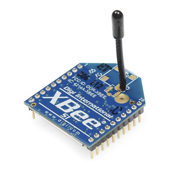
XBees are hugely popular wireless transceivers for a number of reasons.
They're flexible – they send and receive data over a serial port, which
means they're compatible with both computers and microcontrollers (like
Arduino). And they're highly configurable – you can have meshed
networks with dozens of XBees, or just a pair swapping data. You can use
them to remotely control your robot, or arrange them all over your house to
monitor temperatures or lighting conditions in every room.
Covered In This Tutorial
The pair of XBees alone won't get you very far. In most cases you'll want a
separate module to interface with the XBee. You can use an XBee Shield to
connect an XBee to your Arduino. Or you can use an XBee Explorer to
connect an XBee to your computer.
The focus of this tutorial is to explain how to use an XBee Explorer with an
XBee. There are a variety of Explorer boards, all designed to achieve the
same purpose: to create a communication gateway between your computer
and the XBee.
Advertisement
Table of Contents

Related Manuals for Sparkfun Electronics USB Explorer

Summary of Contents for Sparkfun Electronics USB Explorer
- Page 1 Page 1 of 16 Exploring XBees and XCTU Introduction Is your project being dragged down by wires? Looking for an easy transition to wireless communication? If you want reliable, low-cost, bi-directional communication at moderate speeds XBee may be the solution for you! XBees are hugely popular wireless transceivers for a number of reasons.
-
Page 2: Materials Required
Page 2 of 16 The Explorers: USB Explorer, Explorer Dongle, and Serial Explorer. With an XBee Explorer connected between your computer and your XBee, and with the help of the X-CTU software, you can easily configure XBees, test connections, and pass data between your computer and remote XBees. - Page 3 Page 3 of 16 The XBee Explorer USB is the most popular of the Explorers. It’s equipped with a mini-B USB connector, so you’ll need the proper USB cable to connect it to your computer. The highlight of this board is an FT231X USB-to-Serial converter. That’s what translates data between your computer and the XBee.
- Page 4 We’ve written a tutorial detailing How to Install FTDI Drivers tutorial. So go ahead and plug your USB Explorer into your computer, and head on to either the Windows, Mac, or Linux section there. (Ignore the final steps, where Arduino software is invoked.)
- Page 5 Page 5 of 16 Nice work! You’ve assembled the XBee Explorer. You’re ready for the next step. Or, if you’re a power user, looking to get the most out of your explorer, you can check out the more “advanced” assembly below. Advanced Assembly (Totally Optional) For most basic-use cases, all Explorer boards should be good-to-go once you’ve installed drivers.
- Page 6 Page 6 of 16 To add your XBee(s), click the “Add device” icon – – in the upper-left part of the window. That will prompt this screen to show up: Select your communication port. If you’re lucky (or just don’t have a lot of stuff connected to your computer) you may only have one option here.
- Page 7 Page 7 of 16 As you can see by scrolling down the right half, there are a lot of configuration settings available. We’ll get to some of those later. For now, though, verify that the configurable settings visible in the screenshot above match those of your XBee (channel=C, PAN ID=3332, DH=0, DL=0, MY=0).
- Page 8 Page 8 of 16 Each XBee has a unique MAC address, printed on a sticker in the highlighted area. As with the last module, make sure all settings are defaulted (channel=C, PAN ID=3332, DH=0, DL=0, MY=0). That’ll make the next step possible. Quick and Easy Test Click the “Switch to Consoles”...
-
Page 9: Configuring Networks
Page 9 of 16 If that worked, then your XBees are configured to talk to each other! If not, check out the troubleshooting page. That your XBees can talk to each other out of the box is no real surprise. They’re all configured to, by default, be on the same network with the same addresses. -
Page 10: Radio Configuration
Page 10 of 16 destination address of 0x5200, then XBee 1 cannot send data to XBee 2. In this case, only one-way communication is enabled between the two XBee’s (only XBee 2 can send data to XBee 1). We can use X-CTU to easily configure each of those settings. Here’s how: Radio Configuration After the last page, you should already have at least one XBee connected to X-CTU. -
Page 11: Troubleshooting
Page 11 of 16 Here’s an example for setting up the ID, DH, DL, and MY values for a pair of XBees: Setting AcronymXBee 1XBee 2 Channel PAN ID 894B 894B Destination Address HighDH Destination Address Low DL 16-bit Source Address Notice how the only real differences are the DL and MY values, which are flip-flopped on each XBee. - Page 12 Page 12 of 16 There are two options we recommend: discovery or recovery. Discovery The Discover radio devices tool is an extension of “Add devices”. Open the discovery window by clicking the XBee/magnifying glass icon – – in the top-left. Once again you’ll be prompted to select which communication port your XBee is connected to.
- Page 13 Page 13 of 16 Recovery If your XBee seems bricked, don’t worry! You can most likely recover it. To get to the recovery screen, click the Tools icon, and select XBee Recovery. Once again, you’ll need to select your COM port, and you’ll also need to select the product family.
- Page 14 Page 14 of 16 If that doesn’t fix the error, you can probably get away with typing a “0” in that box (usually this pops up for properties like encryption keys or other values meant to be kept secret). After you’ve loaded the default values, you still need to write the settings by clicking the big pencil icon above –...
-
Page 15: Going Further
Page 15 of 16 Short them together for about a second, and then remove the wire. If you’ve done it within the time window provided by XCTU, it should proceed to the next step. If not give it another try…it takes some practice. Resources &... - Page 16 Page 16 of 16 • Getting Started With the RedBot – The RedBot is our popular, Arduino-based robot platform. Once you get it rolling, you can take it a step further by controlling it with an XBee! https://learn.sparkfun.com/tutorials/exploring-xbees-and-xctu?_ga=1.266449614.19394569... 6/24/2015...
Need help?
Do you have a question about the USB Explorer and is the answer not in the manual?
Questions and answers