Table of Contents
Advertisement
Quick Links
SIERRA 25 - 48/230
User Manual V1.0
THE NEW GENERATION OF POWER CONVERTERS
•
DUAL AC AND DC OUTPUT CONVERTER
Commercial Power as default source
•
AC AND DC BACKUP IN A DC ENVIRONMENT
Leverage your existing DC infrastructure
•
ONE STOP SHOP
Wide output power range
•
HARSHEST AC INPUT CONDITIONS
Without compromising the quality of the AC output
Copyright © 2013. Construction electroniques & telecommunications S.A.
All rights reserved. The contents in document are subject to change without notice.
The products presented are protected by several international patents and trademarks.
Address: CE+T S.a, Rue du Charbonnage 12, B 4020 Wandre, Belgium
www.cet-power.com - info@cet-power.com
Belgium, China, India, Luxembourg, Malaysia, Russia, Turkey, United Kingdom, United States, Australia & Germany
www.cet-power.com
Advertisement
Table of Contents

Related Manuals for CE+T Power SIERRA 25-48/230

Summary of Contents for CE+T Power SIERRA 25-48/230
- Page 1 SIERRA 25 - 48/230 User Manual V1.0 THE NEW GENERATION OF POWER CONVERTERS • DUAL AC AND DC OUTPUT CONVERTER Commercial Power as default source • AC AND DC BACKUP IN A DC ENVIRONMENT Leverage your existing DC infrastructure • ONE STOP SHOP Wide output power range •...
-
Page 2: Table Of Contents
Table of content 1. CE+T Power at a glance ......................... 2. Abbreviations ............................3. Warranty and Safety Conditions ......................Disclaimer ........................... Technical care ..........................Installation ..........................3.3.1 Handling ......................... 3.3.2 Surge and transients ...................... 3.3.3 Other ..........................Maintenance ..........................Replacement and Dismantling ..................... - Page 3 8.2.8 Remote ON/OFF......................8.2.9 Internal CAN BUS A and B ....................8.2.10 Shelf rear cover ......................9. Installation of Cabinet (A la Carte) ......................Unpacking the system ......................... Module packing ........................... Removing the cabinet rear protection ..................Hardware Connections ........................ Electrical installation ........................
- Page 4 14. Finishing ..............................15. Commissioning ............................15.1 Check list ............................ 16. Trouble Shooting and Defective Situations Fixing ..................16.1 Trouble Shooting ......................... 17. Maintenance ............................17.1 Access Inview S with Laptop ....................... 17.2 Manual check ..........................17.3 Optional ............................17.4 Manual By-Pass ......................... 18.
- Page 5 Release Note: Release date Version Modified page number Modifications (DD/MM/YYYY) 23/10/2019 First release of the Manual. – Sierra 25 - 48/230 VAC – User Manual – v1.0...
-
Page 6: Ce+T Power At A Glance
CE+T Power at a glance 1. CE+T Power at a glance CE+T Power designs, manufactures and markets a range of products for industrial operators with mission critical applications, who are not satisfied with existing AC backup systems performance and related maintenance costs. -
Page 7: Abbreviations
Abbreviations 2. Abbreviations Enhanced Conversion Innovation Enhanced Power Conversion Regular Digital Signal Processor Alternating current Direct current Protective Earth (also called Main Protective Conductor) Neutral Printed Circuit Board True Redundant Structure Power Electro Static Discharge Main Earth Terminal Manual By-pass Measure Box Battery TCP/IP Transmission Control Protocol/Internet Protocol... -
Page 8: Warranty And Safety Conditions
Warranty and Safety Conditions 3. Warranty and Safety Conditions WARNING: The electronics in the power supply system are designed for an indoor, clean environment. When installed in a dusty and/or corrosive environment, indoor, it is important to: • Install an appropriate filter on the enclosure door, or on the room’s air conditioning system. •... -
Page 9: Installation
Warranty and Safety Conditions 3.3 Installation • This product is intended to be installed only in restricted access areas as defined by local regulations and in accordance with the National Electric Code, ANSI/NFPA 70, or equivalent agencies. • The Converter System may contain output over current protection in the form of circuit breakers. In addition to these circuit breakers, the user must observe the recommended upstream and downstream circuit breaker requirements as defined in this manual. -
Page 10: Surge And Transients
Warranty and Safety Conditions 3.3.2 Surge and transients The mains (AC) supply of the modular converter system shall be fitted with Lightning surge suppression and Transient voltage surge suppression suitable for the application at hand. Manufacturer’s recommendations of installation shall be adhered to. -
Page 11: Eci Technology
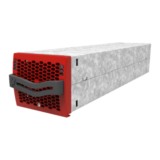
ECI TECHNOLOGY 4. ECI TECHNOLOGY Sierra module built with ECI technology and it is a triple port converter. This module deliver pure sinusoidal output and ripple free DC output from AC mains or battery. The below block diagram gives an explicit description of the topology and its operation. ECI technology has AC to DC, DC to AC, and DC to DC converters to provide constant and disturbance-free output power regardless of the input source. -
Page 12: Epc Mode
ECI TECHNOLOGY 4.1 EPC mode In EPC mode, the AC Mains is the primary source and DC source works as a backup. When AC mains is present, the sierra module takes energy from the AC source and feed to: • AC Load via a double conversation to provide a pure sine wave. •... -
Page 13: Building Blocks
Building Blocks 5. Building Blocks 5.1 Sierra 25 - 48/230 Telecom / Datacom: Input 48 Vdc 230 Vac, 50/60 Hz Output 230 Vac and 48 Vdc Power 3000 VA / 2400 W • The Sierra converter is a triple port converter. •... - Page 14 Building Blocks Frequency (Synchronization range) 50 Hz (47 - 53 Hz) or 60 Hz (57 - 63 Hz) DC Input Data Nominal voltage (range) 48 Vdc (40 - 60 Vdc) Nominal voltage (Adjustable) 53.4 A Maximum input current (for 15 seconds) / 66.8 A / <...
-
Page 15: Sub-Rack
Building Blocks 5.2 Sub-rack • The Sierra shelf shall be integrated in min 600 mm deep cabinets, Inch/ETSI mounting. • The Sierra shelf house max four (4) inverter modules. • The Sierra shelf is designed with individual DC input / output, Common AC input and Common AC output. •... -
Page 16: Measure Box Battery (Mbb)
Building Blocks • USB port is used to access the Inview S configuration and setup files. • Digital Inputs (D1 and D2): Two potential free Digital Inputs are available for customer connections. ƒ Digital Input 1 is assigned for MBP operation if used. ƒ... -
Page 17: Accessories
Accessories 6. Accessories 6.1 Cabinet Powder coated (RAL 7024), 19 inch Flat Pack cabinet with 600 x 600 mm foot print. Cabinet designed for top cabling or bottom cabling. • 1100 mm (600 x 600 mm) • 1800 mm (600 x 600 mm) •... -
Page 18: Mccb
Accessories If an alarm is required for AC output breakers, a help contact attached to each individual breaker is used (OF or SD). The alarm function is common and uses one of the digital inputs on the control unit. The help contact limits the breakers quantity. -
Page 19: System Design
System Design 7. System Design 7.1 A la Carte The A la Carte is pre-assembled and configured as a single phase or three phase system. The system comprises cabinet, converter sub rack, converter modules, manual by-pass, monitor device and output distributions. Single phase system accommodates 1 to 32 modules and provides maximum 96 kVA. -
Page 20: Installation Of Sierra Shelf
Installation of Sierra Shelf 8. Installation of Sierra Shelf • Read safety instructions prior starting any work. • Do not attempt to use lifting eyes to erect the cabinet. • System is preferable handled without modules. • Pay attention to the module position, make sure that modules are repositioned in the same slot. •... -
Page 21: Electrical Installation For Sierra Shelf
Installation of Sierra Shelf Fix cage nuts (4) in the mounting frame. Slide the shelf in position and fix the shelf with the supplied screws (3). Finished. 8.2 Electrical installation for Sierra shelf 8.2.1 Pre requisites • The sub-rack have markings for all terminations. •... -
Page 22: Terminations
Installation of Sierra Shelf 8.2.2 Terminations The below image is termination details of Sierra 25 - 48/230 shelf. AC IN (L) AC Out (PE) Main Earth Terminal AC Out (L) AC IN (PE) AC Out (N) AC IN (N) DC 4 - DC 3 + DC 2 - DC 1 +... -
Page 23: Ac Output Connection
Installation of Sierra Shelf 8.2.6 AC Output connection Model MCB per shelf Cable, min Connector Torque Sierra 25 - 48/230 2P 63 A 3 x 10 mm 5 Nm 8.2.7 Signalling Sierra Shelf - Rear side To Inview S (CE+T COM port) CAN BUS A Remote CAN BUS B... -
Page 24: Internal Can Bus A And B
Installation of Sierra Shelf Functional table for remote ON/OFF function Pin 1-3 Pin 2-3 Status Indication Open Open Normal operation All (Green) AC output (OFF) Closed Open AC Input (Green) DC Input (Green) Open Closed Normal operation All (Green) Closed Closed Normal operation All (Green) -
Page 25: Installation Of Cabinet (A La Carte)
Installation of Cabinet (A la Carte) 9. Installation of Cabinet (A la Carte) 9.1 Unpacking the system CE+T cabinets are always fixed on a pallet, and then packed in a wooden crate. These crates are usually delivered laying flat, horizontally. To unpack your cabinet, we recommend the following method: 1. -
Page 26: Removing The Cabinet Rear Protection
Installation of Cabinet (A la Carte) 9.3 Removing the cabinet rear protection Wooden wedges are fixed at the back of the cabinet to prevent parts from moving and sustaining damage during transportation. These wooden wedges must be removed before going further with the cabinet’s installation and commissioning. -
Page 27: Electrical Installation
Installation of Cabinet (A la Carte) 9.5 Electrical installation • All cables shall be halogen free and rated min 90 deg C. • Wire all positions for future expansion. • Input AC / Output AC / Input DC / Signal cables shall be separated. •... -
Page 28: Cabling
Installation of Cabinet (A la Carte) 9.5.2 Cabling All the cable routings are made through top or bottom of the system. The top cover can be split into two parts to facilitate cabling. The top cover accommodates nylon tie straps used to strap the cables. Note: Do not block the airflow at top of the cabinet. - Page 29 Installation of Cabinet (A la Carte) WARNING !!! Input Neutral is required to operate the Circuit Local Breaker Converter, UPS In TN-S System no 4 pole input switch or Sierra circuit breaker shall be used. If you have to Converter use 4 pole protective device, be aware that the neutral against the ground is floating.
-
Page 30: Dc (X1)
Installation of Cabinet (A la Carte) 9.5.6 DC (X1) • Common DC input per system. • M12 holes in bar. • Max 8 x 240 mm per pole (group). Note: Screws and nuts are not included in the delivery. 9.5.7 Connection table – DC 48 Vdc (X1) Power (kVA) Fuse/CB Min Cable mm... -
Page 31: Signalling
Installation of Cabinet (A la Carte) 9.5.9 Signalling The illustration below shows the X3 relays contacts in a non-alarm state when the system is operational. In this case, the relays are energized and as below. From MBB From Module shelf (Measure Box Battery) From Inview S Major... - Page 32 Installation of Cabinet (A la Carte) Functional table for remote ON/OFF function Pin 1-3 Pin 2-3 Status Indication Open Open Normal operation All (Green) AC output (OFF) Closed Open AC Input (Green) DC Input (Green) Open Closed Normal operation All (Green) Closed Closed Normal operation...
-
Page 33: Operation
Operation 10. Operation 10.1 Converter module Converter Status LED Description Remedial action No input power or forced stop Check environment Permanent green Operation Converter OK but working conditions are Blinking green not fulfilled to operate properly Recovery mode after boost Blinking green/orange alternatively (10 In short circuit condition) Permanent orange... -
Page 34: Inview S - Lcd Display
Operation 10.2 Inview S - LCD Display Once system is powered upon, the Inview S is up and ready for operation. User can access and view the system parameters through the LCD interface. The LCD is a 2.8-inch touch screen, and using stylus provides the best way for navigating pages. -
Page 35: Inview S - Led Indications
Operation 10.2.3 Inview S - LED indications Major Alarm Minor Alarm System Status LEDs code below corresponds to the system and Inview S during normal operation. System Minor Major Description Status Alarm Alarm Working fine Minor alarm Major alarm 10.3 Inview S and Inview S Slot - Web Interface The web interface of both controller Inview S and Inview S Slot is same, and the user can access the controller on the laptop through ETH port. -
Page 36: Interface Areas
Operation 10.3.2 Interface Areas 1 Header 2 Main Page 10.3.2.1 Header The tabs in header provide quick access to the corresponding pages. 1 Home: Tapping on goes to the home page from any page you are accessing in the interface. 2 B readcrumbs: Provide navigation of the page. - Page 37 Operation 10.3.2.2 Home Page 1 AC Input: Tapping on the AC Input region displays the page contain all measurements regarding AC Input. 2 DC: Tapping on the DC region displays the page contain all measurements regarding Battery and DC Output. 3 Power System: Tapping on the Power System region display the page contain regarding system information such as overall system power and also in each phase, configured modules, active modules, and list of detected modules and accessories.
-
Page 38: Inserting/Removing/Replacing - Modules
Inserting/removing/replacing - modules 11. Inserting/removing/replacing - modules 11.1 Sierra Converter • The Sierra converter is hot swappable. • When a new module is inserted in a live system it automatically takes the working set of parameters. • When a new module is inserted in a live system it is automatically assigned to the next available address. 11.1.1 Removal Notice: When one or several converter modules is/are removed access to live parts becomes possible. -
Page 39: Inview S
Inserting/removing/replacing - modules 11.2 Inview S 11.2.1 Panel Mounting Before mounting the Inview S in the system, route all the required connection cables from the system and place near to the Inview S mounting location. 1. Place the Inview S in the panel sheet. 2. - Page 40 Inserting/removing/replacing - modules 5. Replace with new fan and connect supply cord. 6. Place the front cover and tighten the screws on both sides of the module. 7. Check fan for operation. 8. Access Inview and reset the fan run time alarm from within the action menu –...
-
Page 41: Ac Output Distribution
AC Output Distribution 12. AC Output Distribution 12.1 Miniature Circuit breaker Installation/Removal Circuit breakers are normally factory installed. How to add breakers: 1. Insert the short connection cable (10 mm (included)) in the breaker Line-side and tighten. - Up to 40 A breaker - use one connection cable. - 63 A breaker - use two connection cables. -
Page 42: Manual By-Pass (Mbp)
Manual By-Pass (MBP) 13. Manual By-Pass (MBP) Manual By-Pass has to be operated by trained people only. When system is in manual by-pass the load is subjected to mains voltage without active filtering. Output alarm is activated when system is in manual by-pass. The Manual By-Pass cannot be operated remotely. -
Page 43: Manual Bypass Operation
Manual By-Pass (MBP) • MBP - Three independent switch ƒ Connect auxiliary wire from MBP switch (S1) to Digital Input 01 of controller. So that the controller gets information when MBP is engaged. ƒ Connect auxiliary wire from MBP switch (S1) and AC input switch (S3) to Remote ON/OFF terminal in the shelf where controller is installed. -
Page 44: Mbp - Three Individual Switches
Manual By-Pass (MBP) 13.3.1.2 By-Pass to Normal 1. Switch ON the DC power and/or connect batteries. 2. Rotate the MBP Switch (S1) from BYPASS to INTERIM. (Wait until the modules turn on and synchronized, approximately 30-60 seconds). 3. Rotate the MBP Switch (S1) from INTERIM to NORMAL. 13.3.2 MBP - Three individual switches In this model, manual bypass operates through three individual switches - S1 (Manual Bypass), S2 (AC out) and S3 (AC IN). -
Page 45: Finishing
Finishing 14. Finishing • Make sure that the sub-rack/cabinet is properly fixed to the cabinet/floor • Make sure that the sub-rack/cabinet is connected to Ground. • Make sure that all DC and AC input breakers are switched OFF. • Make sure that all cables are according to recommendations and local regulations. •... -
Page 46: Commissioning
Commissioning 15. Commissioning The DC breaker is a protection device. Modules are plugged in a system and DC breaker is then engaged. Please make sure the corresponding DC breaker is engaged in the ON position. Failure to observe this rules will result not to have all module operating when running on DC and have module failure when AC input recover from fault condition. -
Page 47: Check List
Commissioning 15.1 Check list DATA Date Performed by Site System serial number Module serial numbers Inview Serial number ACTION OK/ N.OK Unplug all converters except one converter per phase (Just pull off the inverter from the shelf, to interrupt electrical contacts) Check the commercial AC before closing the AC input breaker. -
Page 48: Trouble Shooting And Defective Situations Fixing
Trouble Shooting and Defective Situations Fixing 16. Trouble Shooting and Defective Situations Fixing 16.1 Trouble Shooting Converter module does not power up: Check AC input present and in range (AC breakers) Check DC input present and in range (DC breakers) Check that the converter is properly inserted Remove converter to verify that slot is not damaged, check connectors Check that module(s) is (are) in OFF state... -
Page 49: Maintenance
Maintenance 17. Maintenance Maintenance should be performed by properly trained people. 17.1 Access Inview S with Laptop • Download system LOG FILE and save - Analyze log file and correct errors • Download system CONFIGURATION FILE and save - Check/correct configuration file according to operation conditions - Check/correct alarm configuration •... -
Page 50: Defective Modules
• The RMA number should be mentioned on all shipping documents related to the repair. • Be aware that products shipped back to CE+T Power without being registered first will not be treated with high priority! (Label shown here is only for representation) -
Page 51: Appendix
Appendix 19. Appendix 19.1 Mains connection, Single phase TN - C - S (400/230VAC) TN - S (400/230VAC) TT (400/230VAC) TN - C (400/230VAC) – Sierra 25 - 48/230 VAC – User Manual – v1.0... -
Page 52: Mains Connection, Three Phases
Appendix 19.2 Mains connection, Three phases TN - C - S (400/230VAC) TN - S (400/230VAC) TN - C (400/230VAC) TT (400/230VAC) – Sierra 25 - 48/230 VAC – User Manual – v1.0... -
Page 53: Inview S With Mbb - Wiring Diagram
Appendix 19.3 Inview S with MBB - Wiring diagram – Sierra 25 - 48/230 VAC – User Manual – v1.0... -
Page 54: Modules - Parameter List
Appendix 19.4 Modules - Parameter List Parameter Description Default Unit Low DC Voltage where a higher value leads the V DC in low start - dV (000) DC/AC converter to re-start Low DC Voltage where a lower value leads to transfer the load from DC IN to AC IN. - Page 55 Appendix Parameter Description Default Unit Set the Inverters system frequency. This Free running frequency - cHz frequency is used when the system is not 5000 (016) synchronized on AC input. Out 1 phase shift - deg (018) Out 2 phase shift - deg (019) Out 3 phase shift - deg (020) Out 4 phase shift - deg (021) Phase displacement.
- Page 56 Appendix Parameter Description Default Unit Allows to open the AC IN inlet relay 0 - normal running in EPC mode. 1 - AC IN inlet relay is open and so the system is AC in mode (041) insulated from the Mains. This parameter can be set to 1 only if repartition is on DC (parameter 036 should be 100) Allow to inhibit the Booster option which...
- Page 57 Appendix Parameter Description Default Unit AC 1 stop power (051) Stops the power of the corresponding AC group. AC 2 stop power (052) The AC input of the modules of this AC group will then be used for synchronisation only, no power AC 3 stop power (053) will be taken.
Need help?
Do you have a question about the SIERRA 25-48/230 and is the answer not in the manual?
Questions and answers