
Summary of Contents for HobbyPCB RS-HFIQ Enclosure Kit
- Page 1 RS-HFIQ Enclosure Kit HFIQ Enclosure Kit Assembly Manual Assembly Manual Jim Veatch WA2EUJ 31 December 2016...
- Page 2 1. Inventory The kit is supplied with the following components: Quantity Description Front Panel PCB Rear Panel PCB Power switch cable assembly with 2-pin header (not used) Power Switch Stick-on feet Lite-pipes #6-32 X ¼” machine screw Extruded case (not shown) Extruded cover (not shown) There are also a few items that you will need for assembly which are not included with the kit: #1 Philips Screwdriver...
- Page 3 2. Preparation Use the black marker to blacken the edges of the front and rear PCBs. Blackening the inside of the opening in the panels also makes the panels look better. Use the black marker to blacken the sides of the lite-pipes. This helps prevent the light from adjacent LEDs from entering the lite-pipe.
- Page 4 4. Attach Power Switch Bend the exposed ends of the power switch cable in to hooks using the pliers. Put one with hook on each of the two contacts on the switch. Since the switch is SPST the wire color is unimportant. Be careful soldering, the switch is easily melted, try only touching the iron to the wire hooks, and do not make contact with the switch terminal.
- Page 5 Attach the rear panel PCB to one and of the enclosure using the 2 bottom screws. Do not put the top screws in at this time. 5. Insert Lite-Pipes into RS-HFIQ PCB Push each of the 4 lite-pipes into the designated location on the front edge of the PCB. The PCB in the photo is a mechanical sample, production RS-HFIQ’s are blue in color and have components.
- Page 6 6. Connect Power Switch Cable The RS-HFIQ PCB has a jumper installed on the power switch header when the board was powered during factory tests. Remove the jumper. If the header on the PCB is similar to the one pictured above it may be necessary to trim the alignment tabs off the connector.
- Page 7 7. Attach Front Panel Attach the front panel with 4 screws and add the 2 remaining screws to the rear panel. 8. Attach Feet Separate the backing from the feet and stick 4 feet on the bottom of the enclosure.
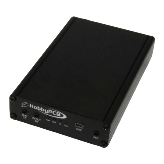
- Page 8 9. Completed Enclosure...
Need help?
Do you have a question about the RS-HFIQ Enclosure Kit and is the answer not in the manual?
Questions and answers