Table of Contents
Advertisement
Quick Links
Advertisement
Table of Contents

Subscribe to Our Youtube Channel
Summary of Contents for PROEL PLCNTR
- Page 1 MANUALE UTENTE –USER’S MANUAL TURTLE SPLITTER PLCNTR Rev. 09/2006...
-
Page 2: Table Of Contents
INDICE DESCRIZIONE..................... 3 CARATTERISTICHE TECNICHE ................ 3 ISTRUZIONI GENERALI ..................3 INDIRIZZAMENTO DMX..................3 APPENDICE: Corrispondenza dei valori di uscita DMX ........5 ATTENZIONE ...................... 5 TABLE OF CONTENTS PRODUCT DESCRIPTIONS ................6 TECHNICAL SPECIFICATIONS................6 PRODUCT INSTRUCTION.................. 6 SETTING DMX ADDRESS .................. 6 APPENDIX: DMX output values................ -
Page 3: Descrizione
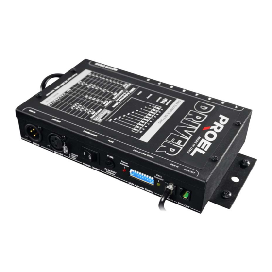
Il TURTLE SPLITTER PLCNTR è l’unità di interfaccia tra faretti Proel PLCCSF e il controllo Proel PLCNCC. Il PLCNTR ha 8 canali di uscita. Ciascun canale può controllare fino a 4 faretti, permettendo così di gestire con una sola unità di interfaccia PLCNTR un massimo di 32 faretti. - Page 4 TABELLA DI INDIRIZZO DMX Num. Canale Switch su ON Iniziale 1,2,3 1,2,4 1,3,4 2,3,4 1,2,3,4 … … 1,2,3,4,5,6,7,8,9, IMPOSTAZIONE INDIRIZZO DMX...
-
Page 5: Appendice: Corrispondenza Dei Valori Di Uscita Dmx
All’accensione dell’impianto, tutti i faretti TURTLE COLOR PLCCSF collegati avviano l’operazione di reset. Tale operazione richiede circa 12 secondi durante i quali i TURTLE COLOR si posizionano sull’effetto ad illuminazione bianca. Terminato il reset, essi tornano alla posizione memorizzata. APPENDICE: Corrispondenza dei valori di uscita DMX 0 - 42 bianco 140 - 172... -
Page 6: Product Descriptions
PRODUCT DESCRIPTIONS PLCNTR is the driver unit of the system. The driver unit has 8 output channels. Each of the 8 output channels can drive up to 4 PLCCSF units, allowing a maximum of 32 PLCCSF to be controlled from each PLCNTR driver unit. Please carefully read this instruction manual for step-by-step setup ad operations. - Page 7 DMX ADDRESS TABLE Start CH Switch ON 1,2,3 1,2,4 1,3,4 2,3,4 1,2,3,4 … … 1,2,3,4,5,6,7,8,9, DMX ADDRESS SETTING...
-
Page 8: Appendix: Dmx Output Values
Once you have completed correctly configuration, apply the power on the system. All PLCCSF units in this system will perform reset function. It may take about 12 seconds for them to resume white. Subsequently, the PLCCSF units will move to the previously set position. APPENDIX: DMX output values 0 - 42 white... - Page 9 Notes:...
- Page 12 PROEL S.p.A. (World Headquarters – Factory) Via alla Ruenia 37/43 64027 Sant’Omero (TE) – Italy Tel. +39 0861 81241 Fax. +39 0861 887862 e-mail: info@proelgroup.com www.proelgroup.com...
Need help?
Do you have a question about the PLCNTR and is the answer not in the manual?
Questions and answers