Table of Contents
Advertisement
Quick Links
Advertisement
Table of Contents

Summary of Contents for LBA GROUP Siteone 3028
- Page 1 Cable Antenna Operators Manual...
- Page 2 Edition Notice ! This publication applies to COMM-connect A/S SiteOne type 3028 Cable & Antenna Analyzer product hardware release “1“and software releases A160808 & D160811. Copyright©2016 All rights reserved to: COMM-connect A/S, Raasigvangen 2, DK-3550 Slangerup Denmark.
-
Page 3: Table Of Contents
Table of Contents General Safety General Information Description Battery and Charging Warranty Connectors Operating Front Panel Keys & Indicators Power On/Off Center Frequency Frequency Span Function Enter / Esc Hold / Copy Dot / Marker Arrows Mode / Menu 0 / Space / Swap Marker Axis 2 / ABC 3 / DEF 4 / GHI / L-Valley... - Page 4 … continued from last page Menus Display mode select Scales Distance to fault Preset measurements System parameters System Info Display modes Start screen SWR / S11 Distance to fault Smith Chart S11 & S21 S11 & Smith R, , Measurements Calibration Specifications Storage functions...
-
Page 5: General Safety
General Safety The SiteOne instrument should only be used for its intended purpose and never be connected to cables carrying hazardous voltages. Never attempt to replace the LiIon batteries, unless you are a trained professional. Great care should be observed preventing polarity reversal and short circuit as the batteries may explode or catch fire. -
Page 6: Battery And Charging
Battery and Charging: The SiteOne features a built-in Li Ion battery pack comprising 2 x 2200 mAh. Charging is fully controlled and automated when using the supplied chargers or a standard USB connection. Full charge is reached after approximately 6 hours with the supplied chargers. The USB/5 Volt regulated charger supplied will allow the instrument to be operated directly from the charger and at the same time charge the batteries when plugged in. -
Page 7: Operating
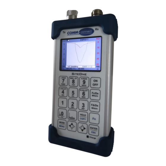
Operating Front Panel Test Connectors Battery Icon* Graphic Display Icon Letters** Keys Charge indicator **Icon Letters *Battery Icon = 10 % = 60 % Alternate function activated = 20 % = 70 % = 30 % = 80 % Display image is on hold = 40 % = 90 % = 50 %... -
Page 8: Keys & Indicators
Keys & Indicators ON / OFF Pressing the ON/OFF button will switch on the instrument. A welcome screen will appear. The instrument will run for the duration of the POWER MIN(1) in the System parameters(5) menu. Fc/De (Frequency Center/Distance-to-fault endpoint) When used in frequency based screens (Fc): Pressing the Fc/De button on the keyboard will present a screen with an entry field ‘Fc:_‘, at the bottom of the screen. -
Page 9: Function
Function Pressing the Function button, will enable the auxiliary functions, marked with a blue color on the buttons. The function icon letter ‘F’ will appear in the lower right corner of the display. Enter / The Enter / Esc button is used to confirm a input, or to leave a menu. Hold / Copy When “HOLD”... -
Page 10: Space / Swap Marker Axis
0 / Space / Swap Marker Axis This key are used as the number 0 when entering new sweep data, as ‘Space’ when entering new alfa numerical data in the menu system and for swapping between marker axis when in measurement mode. This key are used as the number 1 when entering new sweep data. -
Page 11: Pqrs / L-Peak
7 / PQRS / L-Peak This key are used as the number 7 when entering new sweep data and as ‘P’, ’Q’, ’R’ or ’S’ when entering new alfa numerical data in the menu system. When pressed in measurement mode, the ‘L-Peak’ function will place the marker at the highest point of the Left Y-axis. -
Page 12: Menus
Menus Main (0): The main menu gives access to all the submenus. Display mode select This submenu enables the user to select which measurement functions to include in the rolling performed with the ‘MODE’ button. By pressing the number of each of the measurement screens, the user can select whether this function should be part of the mode selection. -
Page 13: Scales
Scales This submenu enables the user to set up the various measurement & graphing parameters, when used in frequency based measurements. Frequency (Fc): Sets the center frequency, similar to using the Fc/De key. Span (FΔ): Sets the frequency span, similar to using the FΔ/Ds key SWR(S11), Sets the maximum of the Y-axis, when... -
Page 14: Distance To Fault
Distance to fault This submenu enables the user to set up the various measurement & graphing parameters, when used in length based measurements. DTF end (De): Sets the endpoint length, similar to using the Fc/De key. DTF start (Ds): Sets the startpoint, similar to using the FΔ/Ds key DTF Velocity Cable Velocity Factor %... -
Page 15: Preset Measurements
Preset measurements The Preset measurements menu contains all parameters for fixed measurement settings and their storage positions. File Mode: Sets the file access mode for the onboard flashdrive 3028: InstrumentFlashdrive PC: FlashdrivePC Operator: Sets the operator name used in the filename, when storing data SaveDir: Sets the directory &... -
Page 16: System Parameters
System parameters This submenu contains general parameters for the usage of the instrument. Power Min: Sets the automatic power off time in minutes Date/Time: Sets the date & time, for use when timestamping measurements DSP Folding: Internal parameter, do not change unless instructed to. -
Page 17: System Info
System Info This submenu contains various system related settings and information. Serial: Displays the serial number of this device Analyzer SW: Displays the software release of the analyzer module Display SW: Displays the software release of the display & auxiliary functions controller Hardware Ver: Displays the HW version of this device Update Analyzer:... -
Page 18: Display Modes
Display modes Start screen The start screen contains the following information: Logo Battery indicator Date & Time Serial number SW release Last frequency & Span setting When restarting the unit, it will always resume the measurement from where it was last used. -
Page 19: Swr / S11
SWR & S11 mode Battery indicator Mode title Left Y-axis title Right Y-axis title (SWR) (REV) Left Y-axis values Right Y-axis values Marker frequency Stop frequency Start frequency Icon Letters Center Y-axis marker value Span Alternating between Left & Right axis This is the classic VSWR screen, used for measuring the impedance match of a antenna. -
Page 20: Smith Chart
Smith Chart Mode Battery indicator Mode title Inductive Center impedance area Span Trace Capacitive impedance area Icon Letters In Smith Chart mode you are presented with a standard Z Smith Chart, capable of showing both the inductive and capacitive properties of the antenna. -
Page 21: S11 & Smith
S11 + Smith Chart Mode Battery indicator Mode title Left Y-axis title (REV) Left Y-axis values Stop frequency Start frequency Icon Letters Center Span In S11+Smith Chart mode you are presented with a standard Z Smith Chart as well as a S11 graph. These two combined datasets further enables you to correctly asses and/or adjust the properties of your antenna. -
Page 22: Measurements
Measurements Connecting antennas: Observe the utmost care when connecting antennas via cables , as these cables can be connected to transmitters and/or power sources! Make sure you have chosen the antenna you intend to test!! Connection to transmitters and/or other sources can destroy the instrument or cause hazardous electri- cal conditions. -
Page 23: Calibration
antenna manufacturers instructions for details. Duplex operation When checking antennas to be used for duplex operation, make sure the antenna SWR is adjusted for the lowest possible SWR in both receive and transmit band. General hints Always refer to antenna manufacturers specification! Antennas may have more than one resonance frequency! A very narrow resonance frequency may indicate resonance of cable instead of antenna resonance (Cable bro- ken or shorted)! -
Page 24: Specifications
Specifications Frequency Center range: 50 kHz to 4.4 GHz Frequency Center Resolution: 1 kHz Frequency Span Range: 0/5 kHz to 4.4 GHz Frequency Span Resolution: 5 Hz to 44 MHz Frequency Accuracy: ±2.5 ppm Distance To Fault End: 1 to 500 meter (1 to 1640 feet) Distance To Fault Start: 0 to 99 m... -
Page 25: Storage Functions
Storage functions The SiteOne instrument contains a built-in SSD drive, which appears on your PC, when you insert the USB cable. The directory is called ‘Data’. This drive contains all the Preset Measurements & the data structure used in the Preset Measurement menu. When the Copy function is activated, the file saving is carried out according to the settings in the ‘Preset Measurements’... -
Page 26: Accessories
Optional accessories Standard accessory kit ( 3028_ACC ) USB Car charger. Coaxial adapters to fit “N” at the Test ports: 2 x N male / FME male 2 x N male / BNC female 2 x N male / TNC female 2 x N male / miniUHF female 2 x N Male / UHF female Soft leather pouch... -
Page 27: Conversion Tables
Conversion table: Return Loss Reflection VSWR In dB Coefficient, r 0.891 17.4 0.794 8.72 0.707 5.85 0.631 4.42 0.562 3.57 0.501 3.01 0.447 2.61 0.398 2.32 0.355 2.10 0.316 1.92 0.251 1.67 0.199 1.50 0.158 1.38 0.126 1.29 0.100 1.22 0.056 1.12 0.032... - Page 28 Type 3028 Operators Manual Version 1 a...
Need help?
Do you have a question about the Siteone 3028 and is the answer not in the manual?
Questions and answers