Table of Contents
Advertisement
Quick Links
Advertisement
Table of Contents

Related Manuals for METREL MI 2014

Summary of Contents for METREL MI 2014
- Page 1 Cable Scanner MI 2014 Instruction Manual Code No.:20 750 429...
- Page 2 Mark on your equipment certifies that this equipment meets the requirements of the EU (European Union) concerning safety and interference causing equipment regulations © 2003 METREL No part of this publication may be reproduced or utilized in any form or by any means without permission in writing from METREL.
-
Page 3: Table Of Contents
MI 2014 Cable Scanner Table of contents 1. Cable Scanner MI 2014 ..................... 4 Section I General information ..................5 2. Safety and operational precautions ................ 5 2.1 Warnings....................... 5 2.2 Battery replacement....................5 2.3 Service and recalibration ..................5 2.4 Maintainance and cleaning ................... -
Page 4: Cable Scanner Mi 2014
MI 2014 Cable Scanner Cable Scanner MI 2014 1. Cable Scanner MI 2014 The Cable Scanner Tester is a portable handheld battery powered instrument intended for testing LAN installations and cables. Main features • Fast Cable Test : most of connectivity tests can be performed by one operater •... -
Page 5: Section I General Information
• External charger is not intended for supplying the instrument without batteries. Warnings Ø Do not charge alkaline batteries. Ø Use only chargers delivered from Metrel or distributor of the test equipment to avoid possible fire or electric shock. Ø In case of blown fuse consult your distributor. -
Page 6: Maintainance And Cleaning
MI 2014 Cable Scanner Section I General information 2.4 Maintainance and cleaning Use a soft cloth, slightly moistened with soapy water, or cleaning alcohol, to clean the surface of the instrument. Leave the instrument to dry completely before using it. -
Page 7: Cable Scanner Description
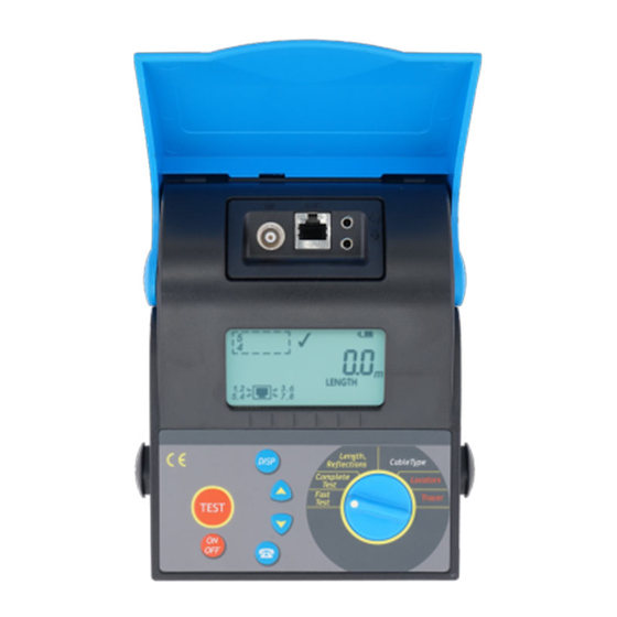
MI 2014 Cable Scanner Section I General information 3. Cable scanner description 3.1 Front panel KEYPAD FUNCTION SWITCH... - Page 8 MI 2014 Cable Scanner Section I General information Front panel layout Function switch selects one of six fuctional/operating menus: Functional Menu Description FAST TEST Fast connectivity and TDR test (no Remote unit needed): - determines cable length or termination - finds cause and location of most frequently cable and...
- Page 9 MI 2014 Cable Scanner Section I General information Description of displayed symbols SYMBOL NAME Wires/ Pairs result field Unselected wires / pairs connected Pair terminated Wires reversed Pair crossed Wires/ pairs shorted, short to shield Unknown connectivity fault Splited pair...
-
Page 10: Connector Panels
MI 2014 Cable Scanner Section I General information Nominal velocity of pulse is displayed Faults / Reflections / Redundant connections are displayed Disconnect the Remote unit (Fast Test) / No Remote detected (Complete Test) Battery indication (change battery if no segment is displayed) 3.2 Connector panels... -
Page 11: Standard Remote Units Description
MI 2014 Cable Scanner Section I General information 4. Standard remote units description 1. Male RJ 45 plug 2. Female RJ 45 connector 3. Identification number 5. Talk remote unit description 1. Female RJ 45 connector 2.Audio jack: Microphone input 3.Audio jack: Phone output... -
Page 12: Section Ii Specifications
Section II Specifications Section II Specifications Ordering number 6. Standard set MI2014 Cable Scanner Cat 5 Patch Cable Metrel PC-2, 1pc Standard Remote #1 Locators #1 - #4 Cable Scanner User Manual Calibration Certificate List of warranty Declaration of conformity 7. -
Page 13: Technical Specifications
MI 2014 Cable Scanner Section II Specifications 8 Technical specifications 8.1 Fast Test RJ45 output only Length (highest distance of all pairs is shown, refer to 3.3 for accuracy) Detection of: - broken wire on connector or cable + distance to fault... -
Page 14: Locators
MI 2014 Cable Scanner Section II Specifications Up to three highest reflections (faults) are reported. Additional error sources that must be considered when measuring length: Uncertainity of NVP (nominal propagation speed) Pulse attenuation at high frequencies effects the accuracy at long distances (over 100m). -
Page 15: General Specifications
MI 2014 Cable Scanner Section II Specifications 9. General specifications 9.1 General Data Display: custom, 85 segments Operating temperature range: 5°C÷40°C Storage temperature range: 0°C÷70°C Relative humidity: 90% up to 40°C declining to 70% up at 45°C Pollution degree: Protection degree:... -
Page 16: Section Iii Cable Scanner Operation
MI 2014 Cable Scanner Section III Cable Scanner operation Section III Cable Scanner operation 10. Fast test The Fast Test function enables fast and convenient checking of the installation. Its main advantage is that the test can be performed by one person, without using the Remotes. - Page 17 MI 2014 Cable Scanner Section III Cable Scanner operation If one or more faults are detected following items are displayed: - the signs - correctly connected pairs - length if available (depends on the kind of test failed, wires 5,1,2,3,6,7 correctly connected...
-
Page 18: Complete Test
MI 2014 Cable Scanner Section III Cable Scanner operation 11. Complete test Complete test checks the installation against all possible connectivity faults. Beside the complete connectivity test the cable identification and cable lenght are performed. Remote units must be connected to the far cable end while performing Complete Tests. - Page 19 MI 2014 Cable Scanner Section III Cable Scanner operation The related wires, type and distance to fault (if available) can be viewed by using keys. During displaying faults the sign is displayed. test failed, shield is broken or not connected...
-
Page 20: Length And Reflections
MI 2014 Cable Scanner Section III Cable Scanner operation 12. Length and reflections This function enables accurate cable length and quality measurements. Up to 3 largest reflections caused by cable damages, impedance mismatches or other reasons are also detected. There are many applications where the Length & Reflection test can be used... - Page 21 MI 2014 Cable Scanner Section III Cable Scanner operation Principle of Cable Scanner Length&Reflections operation To encounter the attenuation effect the reflections amplitudes are compared to the normal attenuation line. This means that a reflection with smaller amplitude at higher distance can be treated as higher then a reflection with higher amplitude at the begin of the measuring range.
- Page 22 MI 2014 Cable Scanner Section III Cable Scanner operation Some typical TDR results Lenght (open cable end) Lenght (shorted cable end,terminated with remote) no result ( cable lenght >300m or cable terminated) Lenght Refl.2 Lenght Refl 1: problem at the...
- Page 23 MI 2014 Cable Scanner Section III Cable Scanner operation If the test failed because of different lengths of measured pairs following items are displayed: - the sign - the length of the displayed pair length test failed By using the key it can be switched between length and amplitude.
-
Page 24: Cable Length Calibrations
MI 2014 Cable Scanner Section III Cable Scanner operation 12.1 Cable Length Calibrations The accuracy of the length measurement is calculated from the time it takes the pulse to travel along the cable and reflect back to the instrument. For this reason the cable NVP (nominal velocity of pulse propagation) must be known. - Page 25 MI 2014 Cable Scanner Section III Cable Scanner operation 1.Select Length&Reflections with rotary switch and press afterwards. The 'Length Calibration' screen is displayed. NVP calibration display 2.Connect the cable of known length to the instrument and set the length with keys.
-
Page 26: Locators - Identification Of Cables
MI 2014 Cable Scanner Section III Cable Scanner operation 13 Locators – Identification of cables Test procedure Locators are used for finding the correct cable connector in wiring closets, patch panels etc. In this mode the instrument decodes which identificator is connected to the far cable end. -
Page 27: Tracer - Tracing Of Cables And Wires
MI 2014 Cable Scanner Section III Cable Scanner operation 14. Tracer – Tracing of cables and wires The in built tone generator can be used together with different Tracers for identifying cable pairs, conductors within a bundle, tracing cables under walls etc. -
Page 28: Talk & Trace Function
MI 2014 Cable Scanner Section III Cable Scanner operation 15. Talk & Trace function The in built Talk & Trace interface enables full duplex voice communication over the cable when using the Talk Remote Unit. The communication works perfectly regardless of the cable length and attenuation. -
Page 29: Breaking Off The Connection
MI 2014 Cable Scanner Section III Cable Scanner operation 15.2 Breaking off the connection The connection can be concluded at any time from the Cable Scanner by pressing key again. The instrument returns to the state it was before the connection. -
Page 30: Cable Type
MI 2014 Cable Scanner Section III Cable Scanner operation 16. Cable type In this menu the active output (RJ45 or BNC) connector and different cable standards/types can be set. The selected cable type is displayed in all functions (excepting the Locator function) For some cable and communication standards just two of four twisted pairs are used. -
Page 31: Reinitialisation (Setting Default Values / Length Unit )
MI 2014 Cable Scanner Section III Cable Scanner operation 17. Reinitialisation (setting default values / length unit ) The default set cable type, default NVP factor and length unit are set if reinitalizing the instrument. Press key while powering on the instrument (rES is displayed) and press afterwards.
Need help?
Do you have a question about the MI 2014 and is the answer not in the manual?
Questions and answers