
Related Manuals for Roth AQUASTOP II


Summary of Contents for Roth AQUASTOP II
- Page 1 Operation Manual LABORATORY COOLING WATER MONITORING UNIT AQUASTOP ® ROTH SELECTION...
- Page 2 To facilitate your orientation in this manual, you find the following symbols: Safety advice General information Wiring- and installing advice Carl Roth GmbH + Co. KG Schoemperlenstr. 3 – 5, D-76185 Karlsruhe · Post office box 10 01 21, Germany Phone: + 49 (0)721/5606 - 0 ·...
-
Page 3: Table Of Contents
CONTENTS FEATURES ............4 SAFETY ADVICE ..........5 SPECIFICATION..........6 OPERATING MODE DESCRIPTION ..... 7– 8 INSTALLATION AND WIRING ......9 – 10 5.1 Installation ..............9 5.2 Connecting to the mains ..........9 5.3 Wiring of accessories ..........9 –10 OPERATION ............11 – 13 6.1 Operating elements and keys ......11 –... -
Page 4: Features
FEATURES Coolig water monitoring unit for use in laboratories, switches off any electrical load up to 230 V AC / 3,5 kW in case of • Undershooting of the chosen minimum cooling water flow: Solenoid valve in the cooling water admission closes, connected electrical load is disconnected with all poles •... -
Page 5: Safety Advice
SAFETY ADVICE 1. Please read this advice carefully. 2 Keep this operation manual for use near the unit. 3. This is an electrical device driven with high voltage, please respect all relevant safety regulations. Mains voltage and every voltage greater than 42 volts is dangerous! 4. -
Page 6: Specification
SPECIFICATION AQUASTOP II Laboratory cooling water monitoring unit ® Art. Nr. CKY2.1 Mains voltage 230 V ± 10 %, 48...63 Hz Electrical connection Power cord with protective earth Nominal rating / nominal current 3,5 kW / 15 A 16 A MT (load) Fuses 0,5 A MT (solenoid valve) 0,2 A MT (controller) -
Page 7: Operating Mode Description
OPERATING MODE DESCRIPTION This unit monitors continuously the cooling water flow and cooling temperature of any critical laboratory equipment operating without surveillance and helps preventing damages caused by unsufficiant cooling action. It can easily be mounted on already existing installations. Cooling water admission is controlled by an solenoid valve fitted onto a normal water tap. - Page 8 OPERATING MODE DESCRIPTION During normal operation, AQUASTOP II works in surveillance mode. The actual temperature of the ® cooling water is shown in the upper part of the display. If an external temperature sensor is used (which automatically disconnects the internal temperature gauge in the flow sensor), make sure that this sensor is located at an appropriate position to measure the critical temperature in the process.
-
Page 9: Installation And Wiring
INSTALLATION AND WIRING 5.1 Installation The installation site must provide easy access for the operator without hazard. Sufficient mechanical stability must be guaranteed, also secure the device from slipping on the installation surface. To ease operation and good visibility of the display, the handle can be used as a support. To adjust the position of the handle, unfasten the screws on both sides of the handle and fasten them again after adjustment. - Page 10 INSTALLATION AND WIRING 5.3 Wiring of accessories Fig.: Back AQUASTOP ® External Pt100 temperature Flowmeter Floating alarm contact max. 230 V / 1 A Serial interface RS-232 Fuse heating 16 A MT Fuse solenoid valve 0,5 A MT Fuse controller 0,2 A MT Power cord Socket solenoid valve 230 V 10 Socket heating 230 V, 16 A...
-
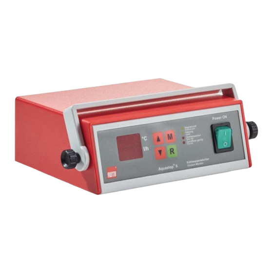
Page 11: Operation
OPERATION 6.1 Operating elements and keys Fig.: Front AQUASTOP ® Multi-function display „UP“-key „Mode“-key LED signalisation operational state Main switch „Reset“-key „DOWN“-key... - Page 12 OPERATION 6.1 Operating elements and keys Key operational functions: Press the UP or DOWN keys (2/7) to increase or decrease the actual value by 1 digit. Move up or down quickly by holding the key pressed. MODE-key, toggles the display from actual value to program mode. Set the duration of the pre-alarm by pressing both „M“...
-
Page 13: Start-Up Procedure
OPERATION 6.2 Start-up Attention: Before switching the unit on, make sure that all tubing is tightly secured and the flow meter is mounted in the right direction of the cooling water stream (see arrow). After verification of all electrical connections, switch the coolant monitor on (5). The green light within the main power switch is now illuminated. -
Page 14: Configuration
SETTING THE OPERATIONAL LIMIT VALUES 7.1 Temperature limit value To alter the temperature limit value, press once the „M“-key (3). On the lower line of the display, „te“ is shown and the temperature limit value shown on the upper display line can now be altered with the „UP / DOWN“... -
Page 15: Temperature Range
SETTING THE OPERATIONAL LIMIT VALUES 7.3 Temperature tolerance value Starting from the normal surveillance mode, press and maintain the „UP“-key (2), then press additionally the „M“-key (3). On the lower line of the display, „tol“ is shown and the temperature tolerance value shown on the upper display line can now be altered with the „UP/DOWN“... -
Page 16: Calibration Of The Flow Meter
SETTING THE OPERATIONAL LIMIT VALUES 7.5 Calibration of the flow meter If AQUASTOP II is delivered together with a flow meter, the unit is already adjusted with that sensor ® and no extra calibration is required. In case of replacement of a flow meter, a new calibration of the unit to that other sensor is needed. -
Page 17: Error Messages
ERROR MESSAGES 8.1 Temperature sensor failure No signal on the temperature sensor entrance: • Check the sensor connector • Check the electrical wiring (might be damaged) 8.2 Flow meter failure Wrong signal on the flow sensor entrance: • Purge the flexible hosing (air bubbles might cause an irritation of the sensor) •... -
Page 18: Serial Data Interface
SERIAL INTERFACE Pin assignment of the connector RING Transmission parameters To be set in accordance with the host computer. Protocol: 9.600 baud 8 bit No parity 1 stop bit One line is sent every second, finished by ‘Return’ (CR) and ‘Linefeed (LF)’. 6 values ASCII are being sent, separated by comma: •... -
Page 19: Ce-Conformity Certificate
CE-CONFORMITY CERTIFICATE DECLARATION OF CONFORMITY This declaration is valid for the following products: Model designation: Coolant monitor Type: AQUASTOP ® Hereby is confirmed, that these products meet in their design and accomplishment as marketed by the manufacturer and if properly used the following EU-directives: EU-Low voltage directive 2004/108/EG EU-Directive for electromagnetic compatibility 2006/95/EG... - Page 20 Global Contact: Carl Roth GmbH + Co. KG · Schoemperlenstr. 3-5 · 76185 Karlsruhe · Germany Phone: +49 (0)721/5606-0 · Fax: +49 (0)721/5606-149 info@carlroth.de · www.carlroth.com All supplies and deliveries are subject to the terms and conditions of sale and delivery of...
Need help?
Do you have a question about the AQUASTOP II and is the answer not in the manual?
Questions and answers