
Summary of Contents for SAB F450
- Page 1 Operation manual Automatic Backflush Filter F450 Translation of the original instructions...
-
Page 2: Structure And Use Of The Operation Manual
Directive 2006/42/EC. The s are continuously numbered and the issue date is placed in the footnote. The manual describes the automatic backflush filter F450 and the handling of the equipment. This manual is to be kept for future use! Copyright © by Georg Schünemann GmbH, Bremen. -
Page 3: Table Of Contents
Maintenance and repair Operation Description General description Technical description 2.2.1 Description of the operational functions 2.2.2 Control of the automatic backflush filter F450 General data Signs and name plates Sound emission Installation and setting to work Before installation Unpack Installation... - Page 4 Automatic Backflush Filter F450 Maintenance Cleaning of strainer insert Flushing disc Pneumatic cylinder Seals Error search and trouble shooting Disassembly and disposal Disassembly Disposal 8.2.1 General regulations for disposal Illustrations Appendix Acceptance report Declaration of conformity Drawings Parts lists Documentation purchase parts...
-
Page 5: List Of Illustrations
List of illustrations Fig. 3-1 Name plate Standard ..................3-1 Fig. 9-1 Components of F450 (G 1/8) ................9-1 Fig. 9-2 Manual control elements and connections of the control unit (G 1/8) ....9-2 Fig. 9-3 Components of F450 (G 3/8) ................9-3 Fig. -
Page 6: Intended And Improper Use
F450 is responsible for all property and personal damage which develop from not intended use. The automatic backflush filter F450 is designed according to the state of the art and the recognized safety-relevant rules. Nevertheless, its use might cause dan- ger to the users or third person’s lives and limbs or impair the filter or other intrin-... -
Page 7: Necessary Diligence Of The Operator
Automatic Backflush Filter F450 Necessary diligence of the operator Please keep this operation manual carefully field and handy at the locations where the filter will be used. Please follow generally effective legal and other binding regulations with regard to the prevention of accidents and the protection of the environment as a sup- plement to this operation manual. -
Page 8: Qualification And Education Of Staff
Automatic Backflush Filter F450 Qualification and education of staff Only reliable personnel should be allowed to perform any work at the filter. The legal minimum age should be taken into account! Employ only trained or instructed personnel and the relevant responsibilities of... -
Page 9: Liability
Inappropriate mounting, starting up, operation and maintenance of the au- tomatic backflush filter F450! Operation of the automatic backflush filter F450 with defective safety devic- Nonobservance of the notices in the operation manual of the automatic backflush filter F450 concerning operation, maintenance, servicing and troubleshooting! ... -
Page 10: Safety
Important instruction! At proper operational the reliability of operation of the automatic backflush filter F450 is ensured. The filter is manufactured according to the safety and industrial safety regulations. During abuse dangers for lives and health of persons and real values of the user is threaten. -
Page 11: Basic Safety Instructions
Automatic Backflush Filter F450 Basic safety instructions Danger through pressure Before maintenance and repair work you have to make sure at any rate that the vessel is unpressurized prior to starting any maintenance work at the automatic backflush filter F450. - Page 12 Burn hazard! Burn of fingers and/or hands Explanation: If the filter F450 is operated in a system, as the Isolate all parts of the system, at those a medium reaches a temperature of more than burn danger exists or 122 °F (50 °C), burn danger exists alone by...
- Page 13 Crush hazard Crush injuries of the fingers, hands and/or feet Explanation: The automatic backflush filter F450 has a min- Keep sufficient safety clearances. imum weight of 37.5 lbs (17 kg), depending up- on model. During transport, the assembly, dis- During transport, assembly and maintenance ...
-
Page 14: Accident Prevention Rules
Check that all cables and connecting lines are attached to the points planned for Before initial operation of the automatic backflush filter F450 the operating per- sonnel have to convince itself of the faultless state by prescribed controls. 1.3.3 Transport/Location Absolutely consider the transportation and attitude information. -
Page 15: Electrical System
Replace damaged or strongly worn components of the compressed air unit im- mediately. All work on the compressed air unit of the automatic backflush filter F450 is to be carried out in the operating stop only. For this the compressed air unit is to be set out of operation and into pressure-free condition. -
Page 16: Safety At Setting Out Of Operation
1.3.6 Safety at setting out of operation Take care that the automatic backflush filter F450 is safeguarded against unau- thorized reenergizing after setting out of operation. Mark the power switch in the control unit by a warning „Out of order“ and secure the power switch against un- authorized restarting with a suitable locking device. -
Page 17: Operation
The determined malfunction may be repaired only with switched off automatic backflush filter F450! The automatic backflush filter F450 may be set into operation again only after cut out the malfunction. A safety check and a functional test are to be carried out. -
Page 18: Description
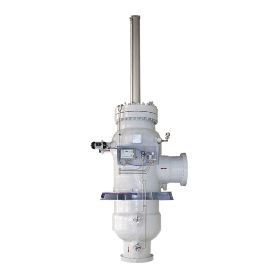
Automatic Backflush Filter F450 Description General description The automatic backflush filter F450 is a versatile applicable, self-cleaning, as far as possible maintenance-free filter to remove individual contamination of high loaded liquids (200 mg/l) from natural sources of water (e.g. seawater, river wa- ter), warming and/or cooling circuits and processes. -
Page 19: Description Of The Operational Functions
Automatic Backflush Filter F450 2.2.1 Description of the operational functions The operation of the automatic backflush filter F450 is divided into the normal operation and the flushing phases: Normal operation The filter is in the normal filtration phase. The flushing valve is closed and the piston... - Page 20 Automatic Backflush Filter F450 Filtration and second flushing phase The flushing valve is open. The pneumatic driven piston, together with the flushing disc, moves into the strainer insert up to a 2/3 depth. The large local increase in velocity in...
-
Page 21: Control Of The Automatic Backflush Filter F450
Automatic Backflush Filter F450 2.2.2 Control of the automatic backflush filter F450 The automatic backflush filter F450 will be controlled via keypad of the electronic control box or remote-controlled and telemonitored by a host over the serial inter- face. The programmable control unit supervises at defined measuring points the pres- sure within the entry region of the filter. -
Page 22: General Data
Automatic Backflush Filter F450 General data Signs and name plates The automatic backflush filter F450 is equipped with signs and a name plate! Always consider the hints, instructions and operating values appropriate on the signs and name plate! Fig. 3-1 Name plate Standard State: 05.02.2016 –... -
Page 23: Sound Emission
Automatic Backflush Filter F450 Sound emission The noise level of the automatic backflush filter F450 is lower than 80 dB(A). The measurement was taken acc. Machine Directive 2006/42/EC, 1.7.4.2 (u). In operation the generation of noise depends on the process conditions resp. the totality of the plant, in which the filter is installed. -
Page 24: Installation And Setting To Work
Before installation Requirements of the conduit system For the full functionality of the automatic backflush filter F450, the following re- quirements must be met and kept: The medium supply pipe and drain pipe must be laid in streamline. -
Page 25: Unpack
chapter 4.1 „Before installation“ in this chapter Crush hazard! The weights of the automatic backflush filter F450, the cover assembly and the strainer insert you will see in the acceptance report. During transport and the assembly, crush injuries of the fingers, hands and/or the feet could happen. -
Page 26: Installation
Automatic Backflush Filter F450 Installation Mounting the filter without mechanically tension In order to guarantee the proper function and optimal lifetime, the filter must be mounted without mechanically tension in the pipe. The filter cover with the pneumatic cylin- der can be delivered separately from fil- ter body. - Page 27 The voltage supply has to be made as a fixed installation. Function failure by wrong handling Guarantee that the automatic backflush filter F450 is not supplied with pressure, as long as the filter is switched off and/or the OPERATION contact is opened, in order to avoid damages of the strainer insert.
-
Page 28: Steps For Setting Into Operation
Automatic Backflush Filter F450 Steps for setting into operation The following procedures have to be done before setting into operation: Before setting into operation check the proper condition of the electric ca- bles and connections of the control (Check the cable connections for fixed fit). -
Page 29: Setting Into Operation
Automatic Backflush Filter F450 Setting into operation Start up the electronic control by switching on the main switch (see chapter 9 “Illustrations”, Fig. 9-2 resp. Fig. 9-4) at the control unit. After switching on the control unit the piston drives to the upper end position and the filtration can be started also at any time by pressing the key Spülen/Flush. -
Page 30: Testing And Adjusting Of The Operating Parameters
Automatic Backflush Filter F450 Testing and adjusting of the operating parameters Implement the following steps, in order to check the proper function of the filter. 4.6.1 Switch on control with the power switch, first flushing phase/pre-flushing check By activating the power switch the control automatically switches into filtration operation (default setting). -
Page 31: Check Of Proper Terminating Of Flushing
Check of proper terminating of flushing The flushing valve closes some seconds after the flushing disc is moved back in- to the initial position. The LCD display at the control indicates “F450“ and “Filtra- tion” in the change with the remaining interval time T1. -
Page 32: Adjustment Of Time And Date
The time and date will be buffered over 5 hours in case of a power blackout. After the switch-on of control system the time and date has to be adjusted in the parameter menu (see specification of control unit, appendix „Filter control F450“). 4.6.7 Operating parameter Recommended alignment of the operating parameters (reference value –... -
Page 33: Service And Operation
Automatic Backflush Filter F450 Service and operation The controlling of the automatic backflush filter F450 is done by an electronic control unit. The parameters will be entered via keyboard or the integrated serial interface box. The control unit presents in some sub items different operating possibilities. -
Page 34: Maintenance
Automatic Backflush Filter F450 Maintenance In this chapter all necessary maintenance of the automatic backflush filter F450 is described in detail. It is absolutely necessary to ensure that the filter is not under pressure before starting maintenance, because the automatic backflush F450 is a pressure ves- sel and that it is drained, if the filter shall be opened. -
Page 35: Pneumatic Cylinder
Automatic Backflush Filter F450 Pneumatic cylinder After removing the flushing disc the pneumatic cylinder may be completely removed by loosening the four flange screws on the cover and inspected for damage. Seals The cover seal is accessible if the filter is open and may be inspected of damages and replaced if necessary. -
Page 36: Error Search And Trouble Shooting
Automatic Backflush Filter F450 Error search and trouble shooting This chapter describes possible potential malfunction, their causes and how to repair. Prior to any maintenance and repair work, the filter has to be de-energized and safeguarded against unintentional reenergizing! The zero potential is to be determined! Neighbouring energized parts are to be... - Page 37 The diameter of the orifice is com- eters are not the same puted by SAB on the basis of as those which have throughput in m³/h and the pump been designed by di- characteristic.
- Page 38 Automatic Backflush Filter F450 Malfunction Possible cause Arrangements Continuous Air in the differential Vent differential pressure flushing pressure switch switch (see chapter „Illustrations“) in assistance of the vent screws (see Fig. 9-1 resp. Fig. 9-3 / 8c). In case of ATEX-specification the...
- Page 39 Automatic Backflush Filter F450 Malfunction Possible cause Arrangements Continuous Diameter of orifice or Verify the dimensioning, because flushing flushing disc underval- the diameter has effects on the ued, filter insert contami- back flushing quantity and thus on nated the cleaning behaviour. If the op-...
- Page 40 Automatic Backflush Filter F450 Malfunction Possible cause Arrangements Option Flushing valve does not Check function of flushing valve Valve error open resp. not close (Fig. 9-1 resp. Fig. 9-3 / 6) . Check compressed air supply. Proximity switch defec- Check function of end position tive/wrongly wired switch.
-
Page 41: Disassembly And Disposal
Automatic Backflush Filter F450 Disassembly and disposal Disassembly The compressed air unit is to be set out of operation and into pressure-free con- dition. The compressed air unit is safeguarded against unintentional repressuring and marked by a sign „Work on compressed air unit“. Additionally also the elec- trical system is to be set out of operation and safeguarded against resetting. -
Page 42: Illustrations
*Compressed- Air connections for components of the same name **Accuracy description in Fig. 9-2 ***Optional equipment Differential Pressure Measurement with Transmitter 4 – 20 mA Fig. 9-1 Components of F450 (G 1/8) State: 05.02.2016 – 1.3 Georg Schünemann GmbH, Bremen... - Page 43 Automatic Backflush Filter F450 Key <Spülen/Flush> LCD-Display Control time LEDs Spülen Key <EIN/AUS ON/OFF> EIN/AUS Flush ON/OFF Key <Enter> Enter Power switch Keys <ARROW UP> and <ARROW DOWN> Switch into Parameter Mode Compressed-Air Connection Drive Flushing Disc downward Tasten <PFEIL RAUF>...
- Page 44 *Compressed- Air connections for components of the same name **Accuracy description in Fig. 9-4 ***Optional equipment Differential Pressure Measurement with Transmitter 4 – 20 mA Fig. 9-3 Components of F450 (G 3/8) State: 05.02.2016 – 1.3 Georg Schünemann GmbH, Bremen...
- Page 45 Automatic Backflush Filter F450 Key <Spülen/Flush> LCD-Display Control time LEDs Spülen Key <EIN/AUS ON/OFF> EIN/AUS Flush ON/OFF Key <Enter> Enter Keys <ARROW UP> and <ARROW DOWN> Switch into Parameter Mode Compressed-Air Connection Drive Flushing Disk downward Tasten <PFEIL RAUF> Compressed-Air Connection Drive Flushing Disk upward...
- Page 46 Automatic Backflush Filter F450 COMPRESSED AIR COMPRESSED AIR HOSES/PIPES HOSES/PIPES OPTIONAL: SINGLE ACTING ACUATOR MOUNT AERATION NIPPLES POINTING UPWARDS DIFFERENTIAL PRESSURE SWITCH WATER HOSES/PIPES Fig. 9-5 Air and water connections State: 05.02.2016 – 1.3 Georg Schünemann GmbH, Bremen...